With the ‘rolling chassis’ of my CNC router together, my focus shifted to mounting cable chains on the three axes to support all the wiring.
I ordered all my cable chains from IGUS – they come at a premium price relative to the Chinese cable chains you find on eBay, but you the quality is high and you have a lot of options – width, height, enclosed or open, snap-open on either the inside or outside radius, minimum bend radius, mounting options on either end, internal dividers, and exact length. The removable slats can pivot open in either direction, and can be easily removed entirely. They snap in very securely and so far none of them have broken in the process of removal or reinstallation.
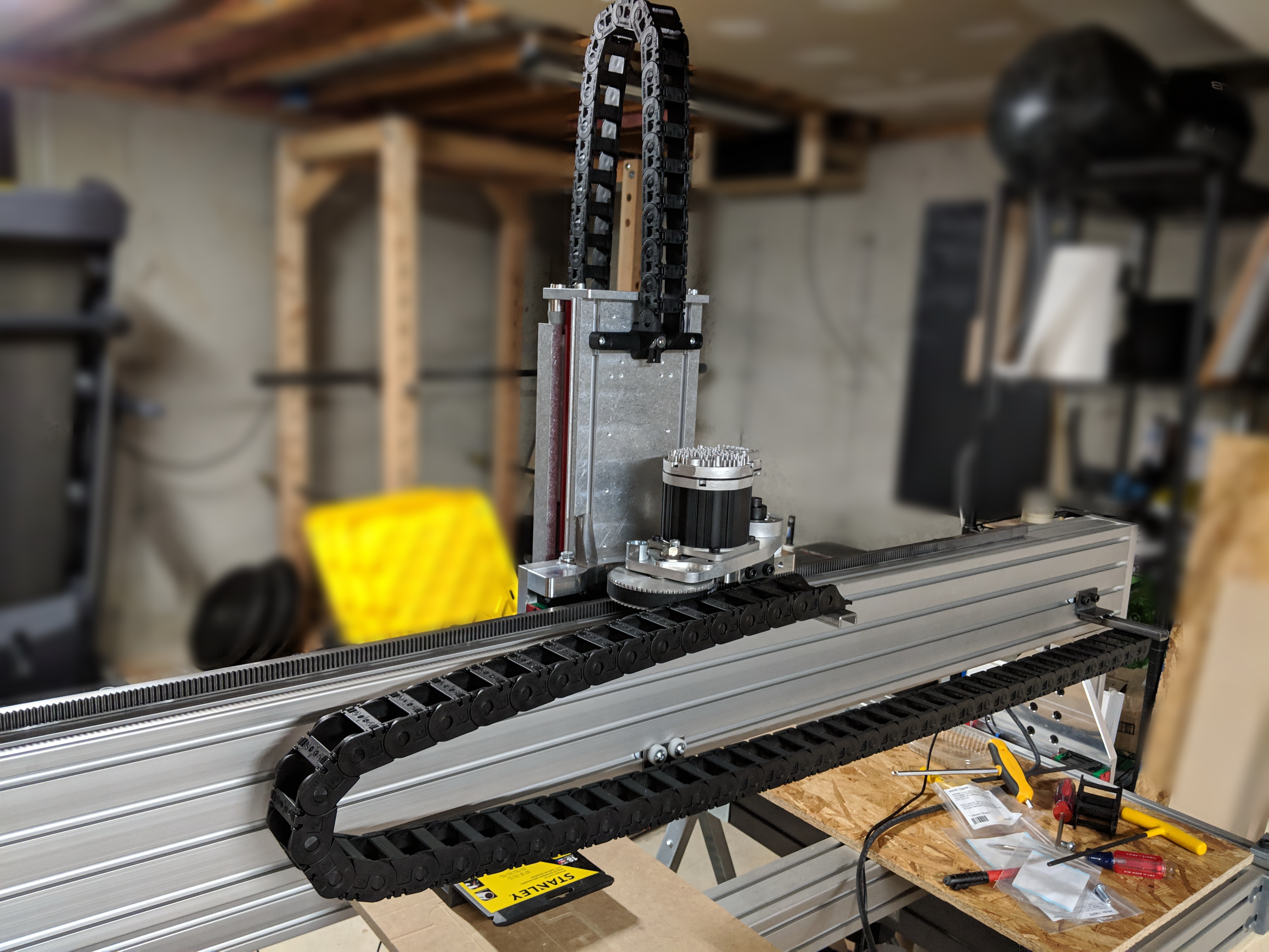 The X cable chain is naturally the longest, and I also didn’t want it to be able to sag down below the bottom of the gantry, where it might catch on something while the machine is running. I mounted it at either end using simple brackets that I welded up from steel angle iron and U-channel. I later ended up switching to a piece of 1515 extrusion for the end that mounts to the gantry (see later photos). Pictured here, there is a small L bracket which supports the chain mid-span, but for a more robust solution I subsequently added a sheet metal tray that provides better support. I also elected to flip the X cable chain around the other way relative to the first photo, so that I could install the control box(es) on the right-hand side of the machine.
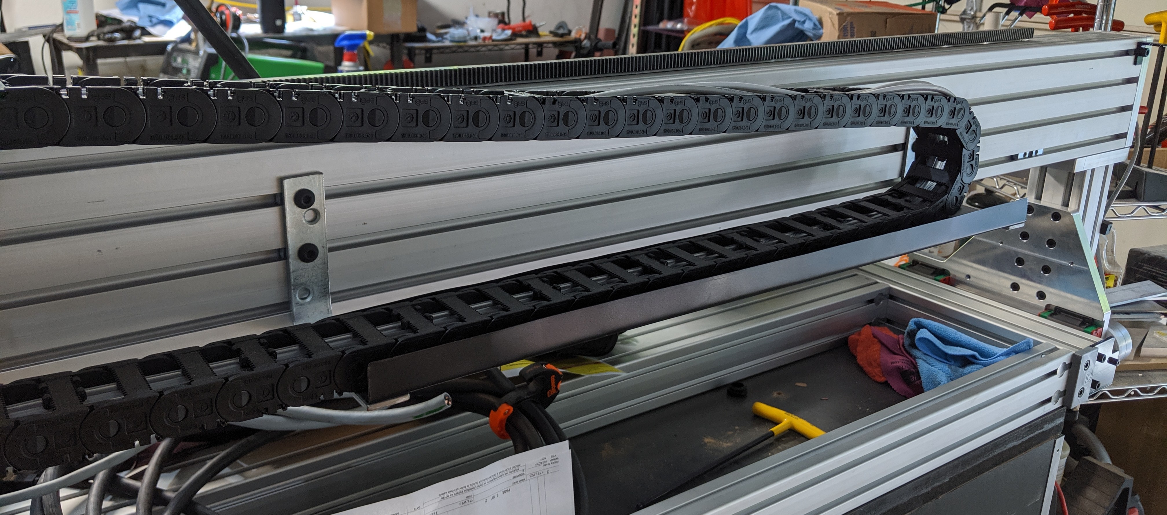 The support tray is simply thin sheet metal, bent into a channel shape using a bending brake, painted black and mounted using some off-the-shelf steel L-brackets (redrilled to match the T-slots in the extrusion)
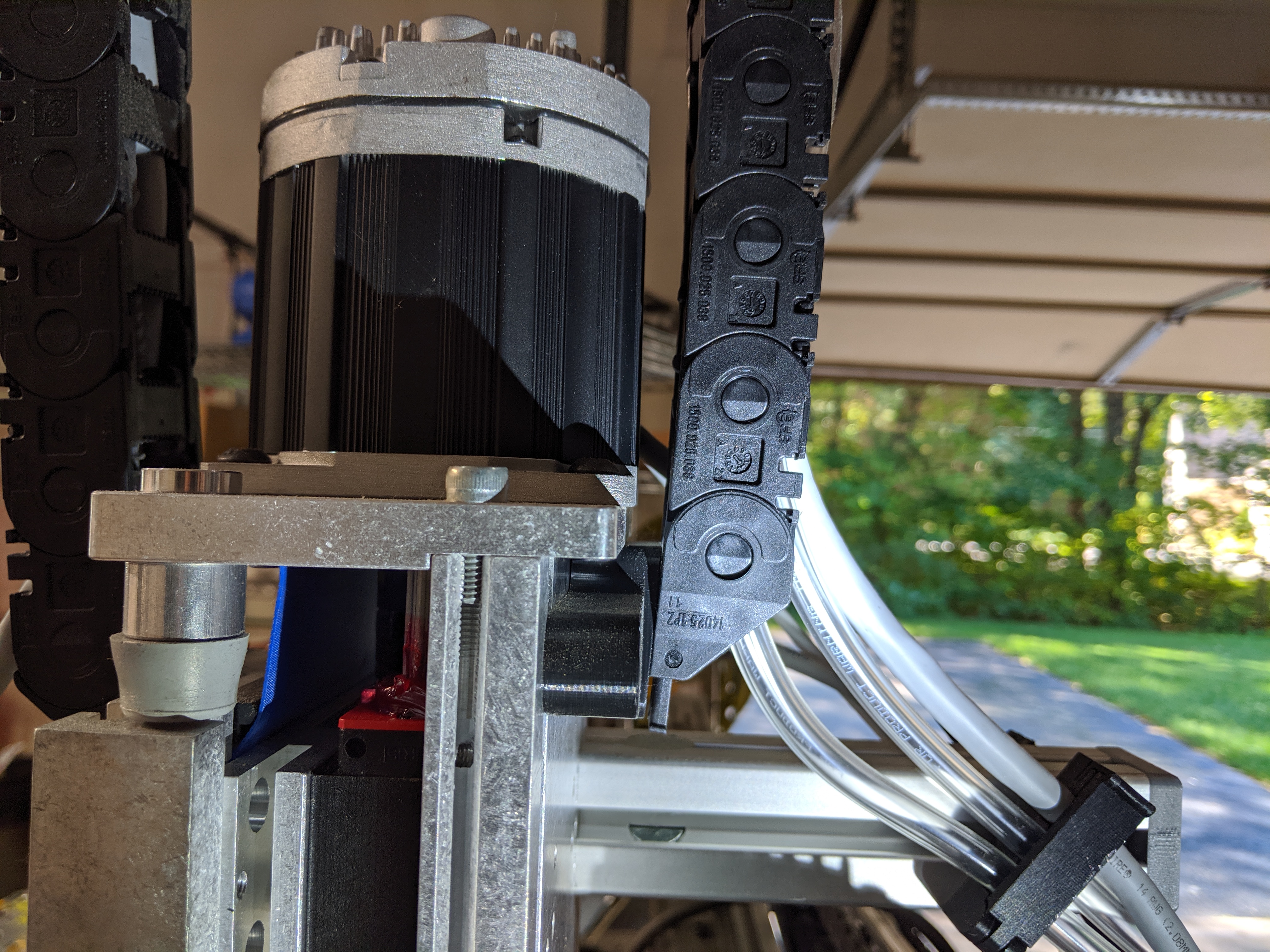
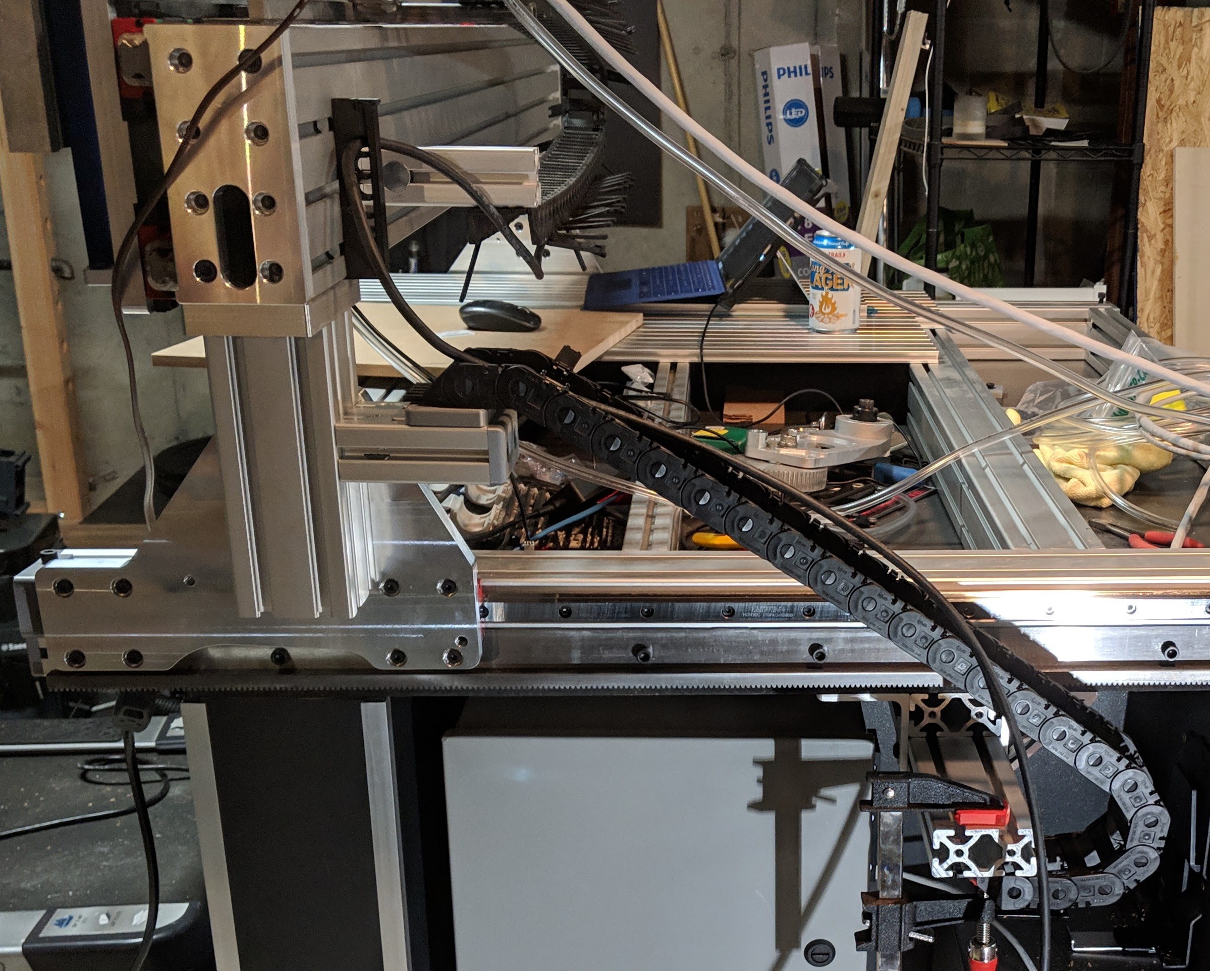
I used a short length of 1530 extrusion anchor fastened to the riser extrusion to mount the top of the Y cable chain. While I was at it, I switched the bottom mount of the X chain to a piece of 1515 extrusion for more versatility. The Y chain is mounted using another 3D-printed adapter bracket, since the mounting holes in the chain end don’t match the width between the T-slots. The bottom end of the Y cable chain mounts to an assembly made of two pieces of 1530 extrusion, mounted to the underside of the base with standard angle brackets. This arrangement is strong and adjustable so it was easy to get the chain positioned just right.
Incidentally, this is the second Y cable chain I tried – the first had an unnecessarily small bend radius, and turned out to be too narrow to comfortably fit all the cables and hoses
IGUS does sell an array of different dividers that can be installed in the cable chains to partition them to keep wiring organized. I found it a bit confusing to try to spec and order those, and I expect they may have been a bit expensive anyway, so I came up with my own design and 3D printed several dozen of them.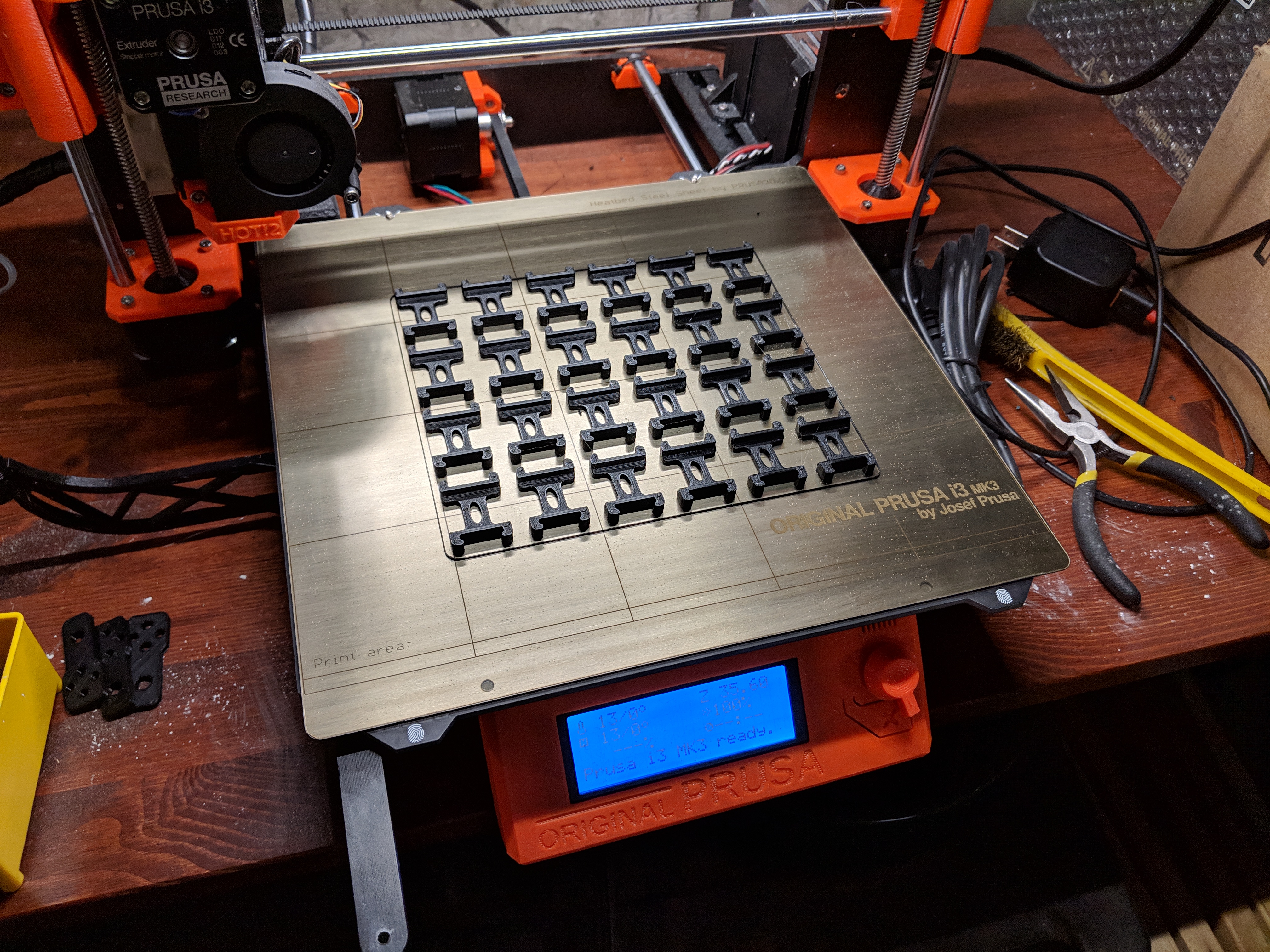 These snap onto the slats of the chain – I placed them every 3rd link or so. These were a tremendous help in achieving clean cable runs, as well as segregating signal lines (sensitive) from power lines (noisy) and the water lines for the spindle.
I also 3D printed a number of cable clips that bolt to the frame extrusion and clip shut. Each of these clips was designed with slots sized specifically for all of the cables/hoses that go through it.
 I placed several such clips in various spots across the machine – anywhere that cables needed support. The nice thing about these being 3D printed is that any time I need to add or change anything, it’s a simple matter to just modify the design and print another.
For all of the Clearpath servo wiring, I elected not to purchase the power and control cables from Teknic – they’re nice, but they come in fixed lengths, so I would end up with a lot of excess cable to deal with. Instead, I ran SJOOW rubber-jacketed 16/2 power cord for the power wiring, and stranded shielded ethernet cable for the control signal wiring. In a later post I’ll detail my control electronics, but suffice it to say that the control wiring connects to my breakout board via RJ45 connectors, so I simply bought off-the-shelf ethernet cables, cut them in the middle to length, and terminated that end with the appropriate Molex Mini-Fit Jr connector to go into the servo.
One big plus of the pre-made wiring that Teknic sells is that the connectors have an overmolded strain relief. I wanted to emulate that, but don’t have any capability for injection molding, so I did some experimentation. I 3D printed backshells in TPU filament, which is flexible, in two halves (clamshell). Those get clamped over the back of the connector, with some silicone in there for good measure. The beauty of using a thermoplastic like this is that with the backshell in place, I simply ran a soldering iron around the seam which sealed the two halves together. This worked great – the two halves show no signs of pulling apart without being cut. 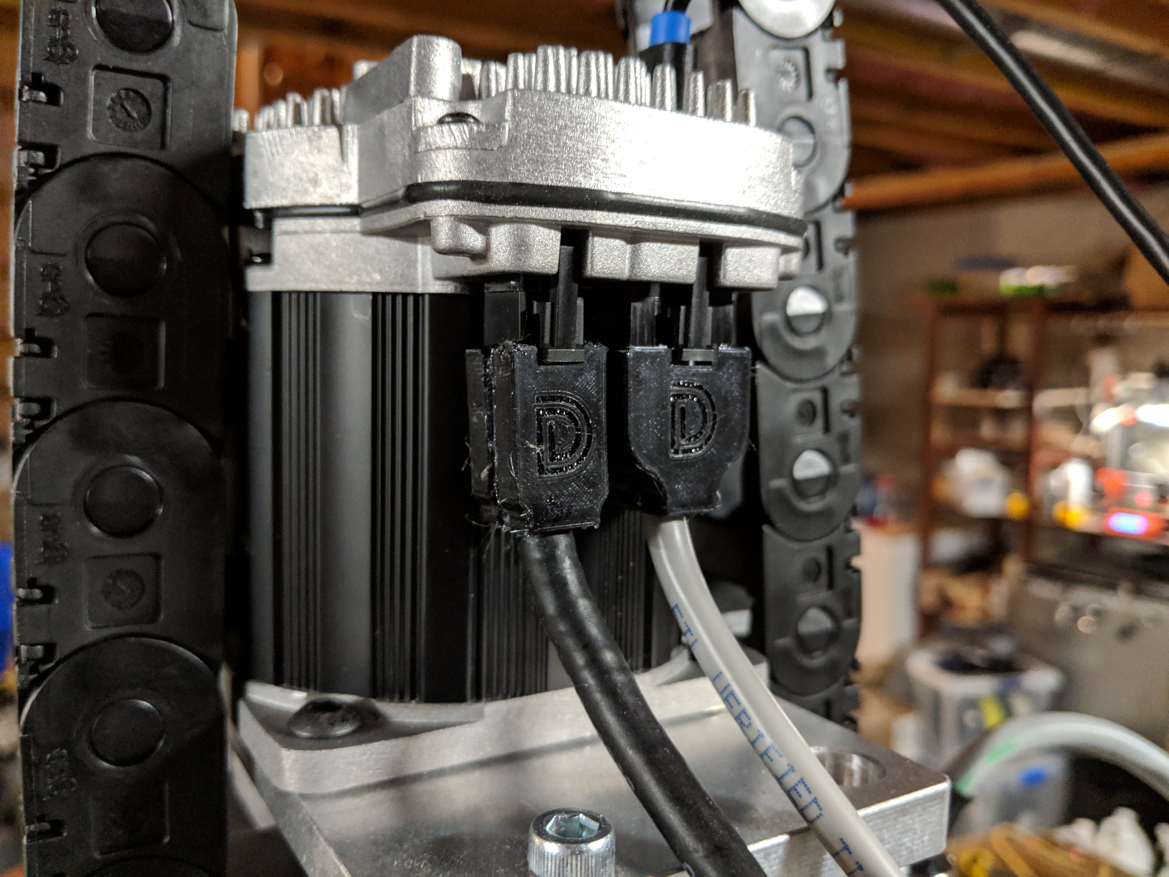
I had to do some adaptation to connect water lines to the spindle. The fittings on this (imported) spindle are compression style, meant for 6MM ID tubing. The barb is rather small, and I was not happy with how secure they were(n’t) when I tried to stuff 1/4″ tubing on there. I was able to source small enough tubing, but I didn’t like how thin-wall it was. My solution was to use a short length of that tubing to get out of the spindle, up into the Z cable chain, and then an inline barb fitting adapts it to standard flexible clear 1/4″ ID PVC tubing with a sufficient wall thickness that it’s not so prone to kinking. I also incorporated a piece of spring stock over the thin-wall silicone tubing to add more resistance to pinching or kinking.
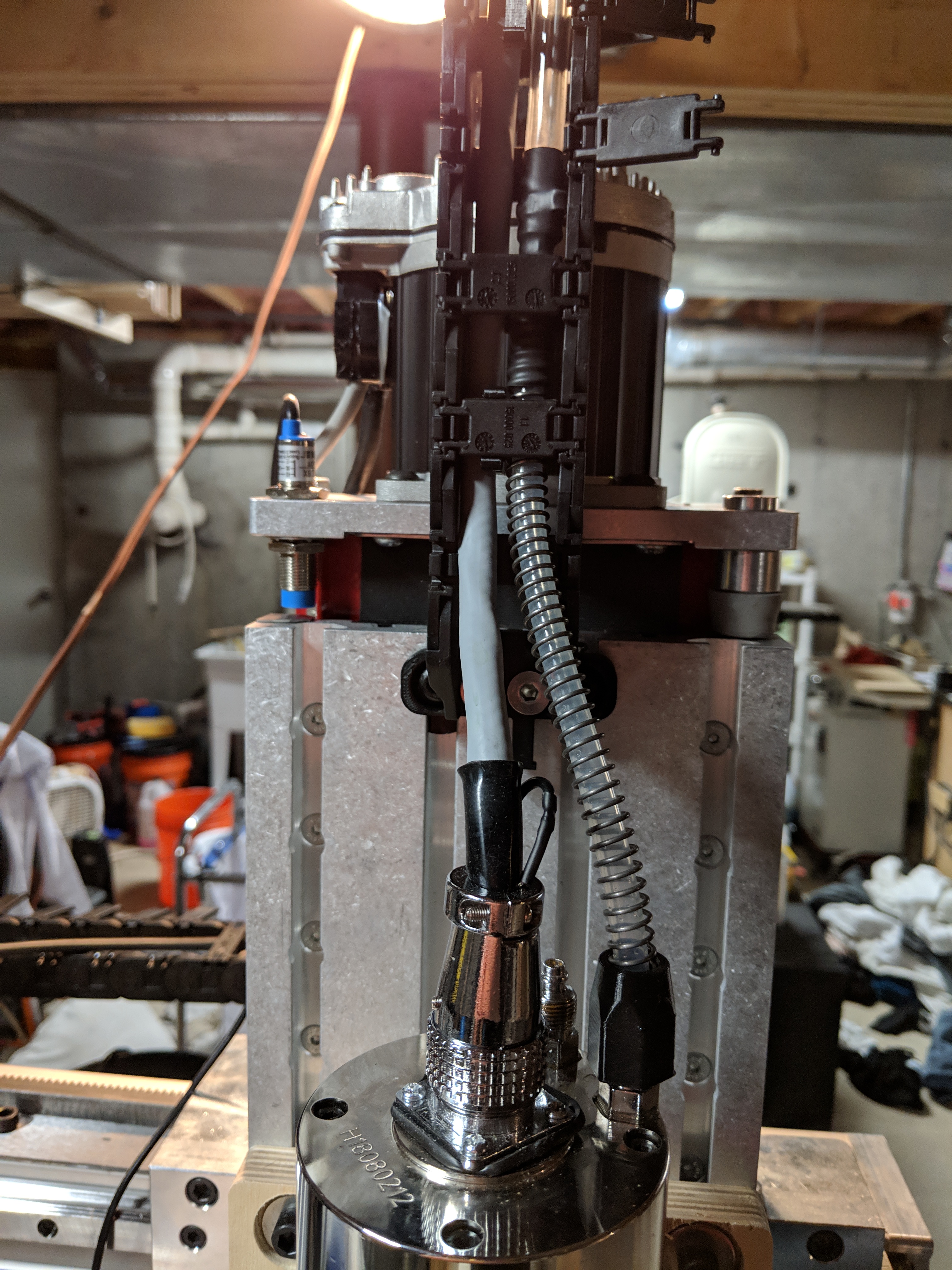 I’m still not completely thrilled with these water line connections – because the tubing is so soft and thin, even with the compression nuts tight it would still be possible to tug the hoses off the barbs. Someday I will revisit and improve that, but for now it’s held up.
More to follow on the rest of the water cooling loop in a future post…