VFD Installed

Initial VFD Integration

My initial spindle integration was done on a borrowed spindle, with a borrowed Huanyang VFD (both of the type found all over eBay), side-by-side with the Lenze SMV VFD that I first purchased for my machine.  This was mostly a matter of getting over the learning curve of properly programming the various parameters of each VFD.  Here, since the spindle was running only for seconds at a time and under no load, the spindle was uncooled – but try that only at your own risk.

Initial VFD integration
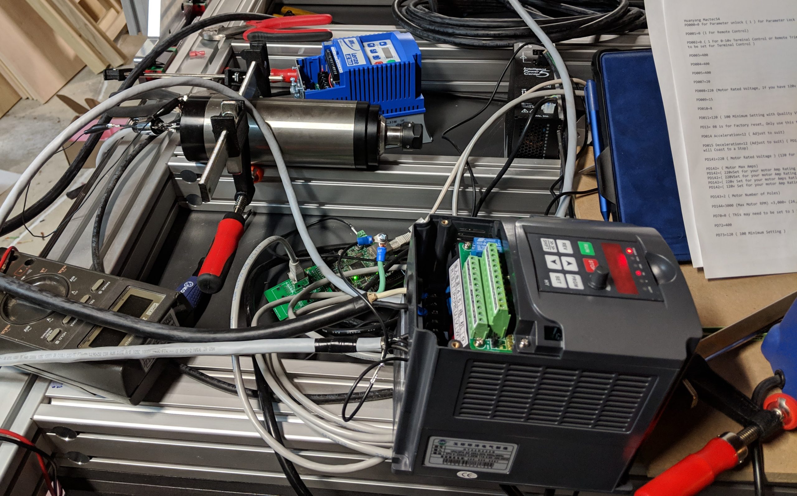
I did get both VFDs working, but ultimately the Lenze VFD fell short of expectations for me.  The quality was good and it was easy enough to work with, but the main selling point of this unit (which is considerably more expensive than eBay VFDs) is that it offers vector speed/torque control, which is supposed to allow a much broader range of spindle speeds, maintaining respectable torque down to much lower RPMs than a traditional VFD.  
However, I was never able to get the vector modes working.  There’s an auto-tune function that is supposed to determine the motor parameters for vector control – but every time I tried it, it either failed to tune, or it completed but wouldn’t run the spindle.  The other option is to enter motor parameters manually, but no such parameters were published for this type of eBay-grade spindle. Inquiring with the seller got me absolutely nowhere – they didn’t even understand the question.

The final nail in the coffin for the Lenze VFD was that certain valuable features – namely dynamic braking and modbus communications – are sold as add-on modules.  Unfortunately, they’re also quite expensive – over $100 each – which would have pushed my total VFD cost to over $600.  

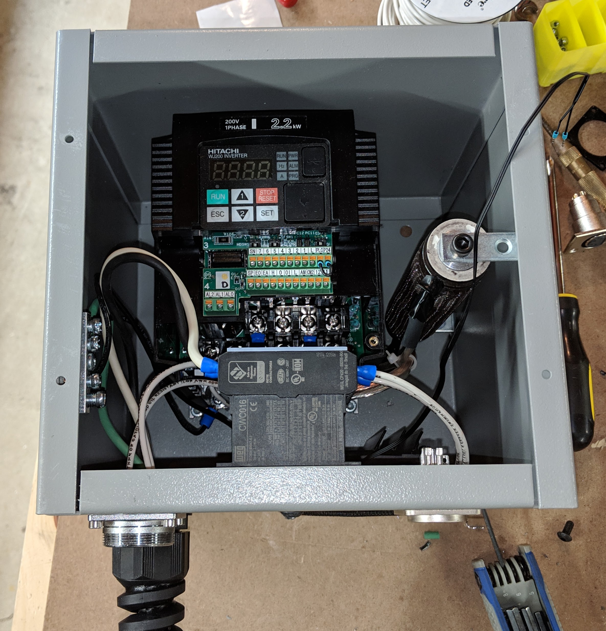
That put me over the edge, so I offloaded the Lenze VFD on eBay and bought a Hitachi WJ200-022SF to replace it.  The Hitachi is very comparable in price to the Lenze, but it natively supports modbus control and it contains a built-in braking unit.  Braking still requires adding an external braking resistor, but that’s a problem that can be solved with careful selection of high-power resistor – which can be found cheaply as surplus. 

This leads me to an important lesson learned – there are compact chassis-mount, aluminum-body wirewound power resistors readily available – usually gold-anodized.  I tried to use them, but each one failed (open-circuit) during the very first braking event.  These resistors are commonly rated for 50W, but the job of braking a spindle involves a very short, high-current spike lasting a second or less – somewhat of an impulse.  In my experience, that proved to be too much for the resistive wire coil in these resistors.  

DO NOT use this type of power resistor for braking!

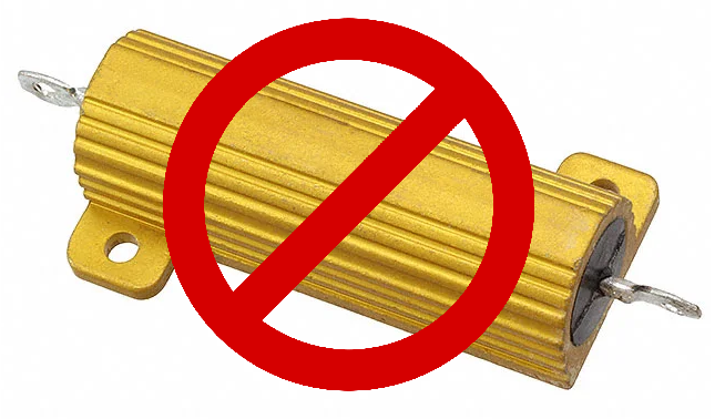
Instead, look for tubular-style ceramic power resistors, consisting of wire or metal ribbon wound on a hollow ceramic core.  They’re quite a bit larger – typically 6 to 8 inches long and an inch or more in diameter – but they are able to absorb the current impulse involved in use as a spindle braking resistor.    

The inertia of a typical 400Hz router spindle is not that large, so the total amount of kinetic energy that needs to be dumped into the braking resistor per braking event is not tremendous.  In practice, I found that the resistor will warm up enough to feel the difference by touch, but even after repeated braking cycles in quick succession it still didn’t get hot enough to be concerning.

Why is braking important?

Spindle braking is something I didn’t know I needed before I bought my first VFD, but the value became apparent pretty quickly.  High-speed spindles necessarily have decent bearings and balance, so once spun up to 24000 RPM they can take many seconds to spin down to a stop if allowed to freewheel.  

Personally, that was enough to get me concerned about safety – in the event of a problem during operation, when the machine needs to stop due to a detected fault or operator intervention, I’d really prefer for the spindle to not keep spinning for 10+ seconds.  (Of course, if it was actually cutting material at the time, then it would stop much more quickly)

VFDs can actively slow the spindle down, faster than the inherent friction would otherwise achieve, but their ability to do so is relatively limited without somewhere to dump energy.  VFDs work by taking the AC input power (240V 60Hz single-phase, in my case) and rectifying it to high-voltage DC which goes into very large storage capacitors.  The VFD uses power transistors (e.g. IGBTs) to drive each of the 3 motor phases with an AC waveform, which is synthesized from the HV DC.  When braking, the spindle motor actually acts as a generator, and the VFD is able to dump power from the spindle back into the HV capacitor bank, which charges these capacitors to a higher voltage than the nominal level of the rectified input power.  

Here a limitation comes in, because the capacitors, transistors and all other associated circuitry can only tolerate just so high a voltage.  Any decent VFD is smart enough to protect itself from overvoltage by stopping the braking action – usually manifesting as a brief period of braking, followed by tripping a fault condition – after which the spindle freewheels the rest of the way to a stop.  Braking using this method can still achieve a modest improvement in deceleration time, but in my experience it was still a few seconds at best.

Dynamic braking solves this problem with the use of another high-power transistor on the HV DC bus, which can turn on once the DC voltage rises above some threshold, dumping the excess energy into the external high-power resistor.  With this method, braking can be substantially faster – I’ve got my deceleration time set to about 1 second.  I’ve tested it to even faster values, but it starts to get kind of violent – more like slamming the spindle to a stop, which doesn’t sound good and can’t be great for the spindle.
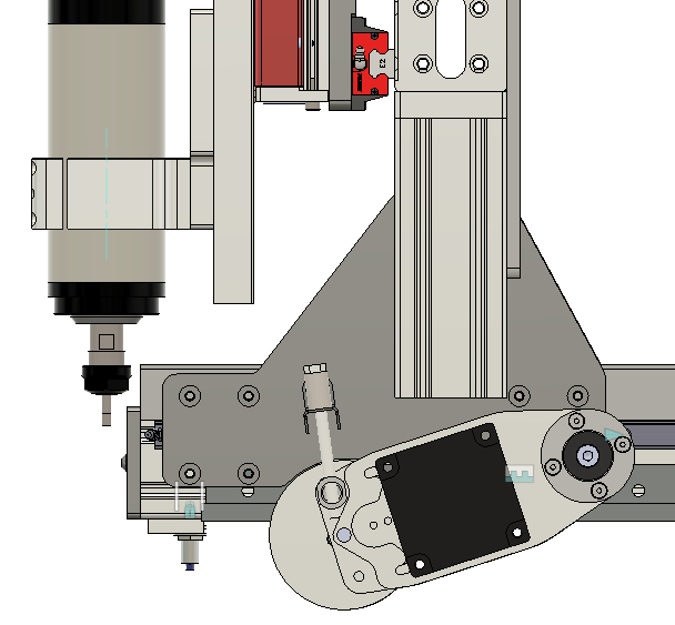
VFD Installation

VFD Installed
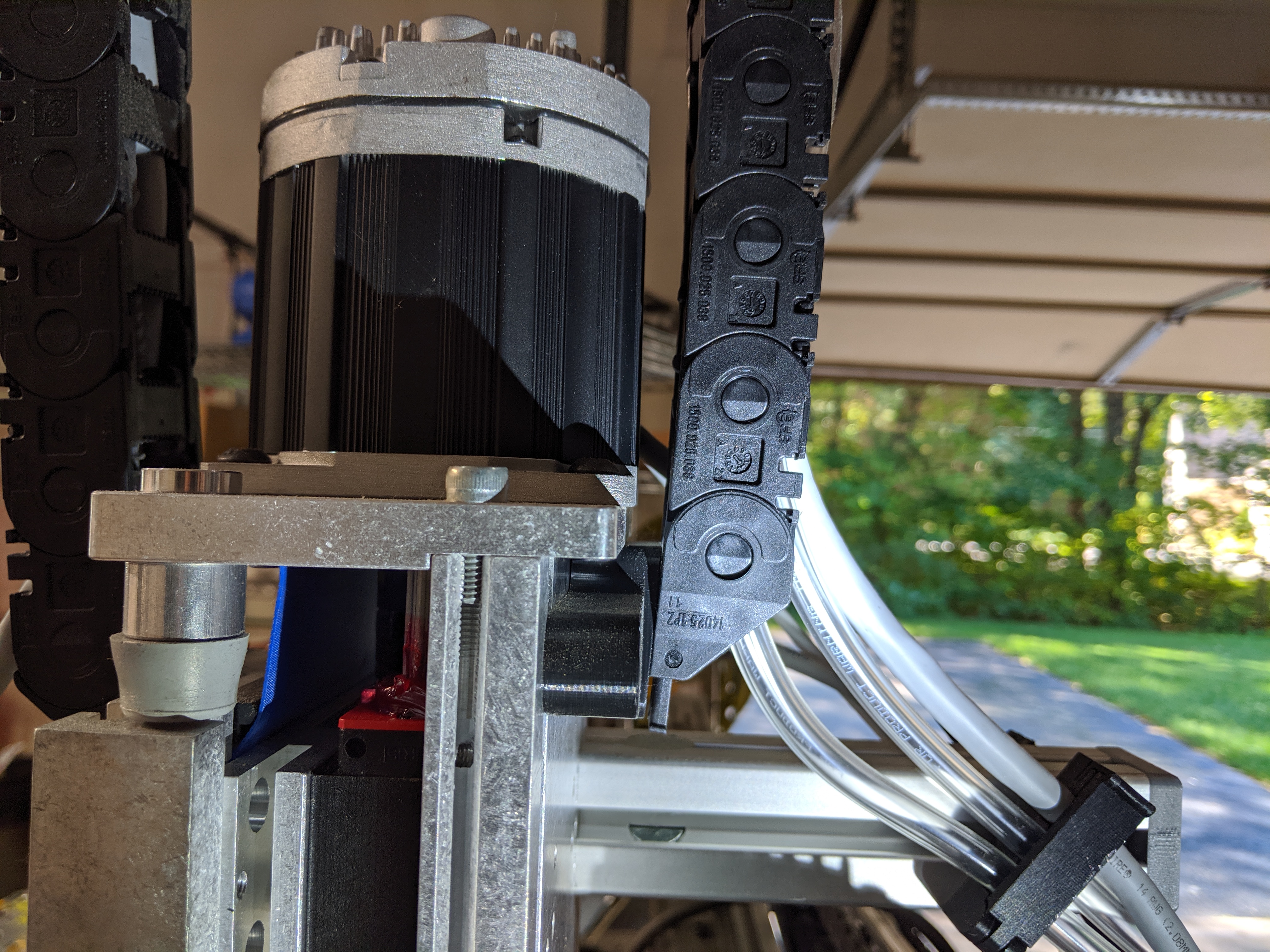
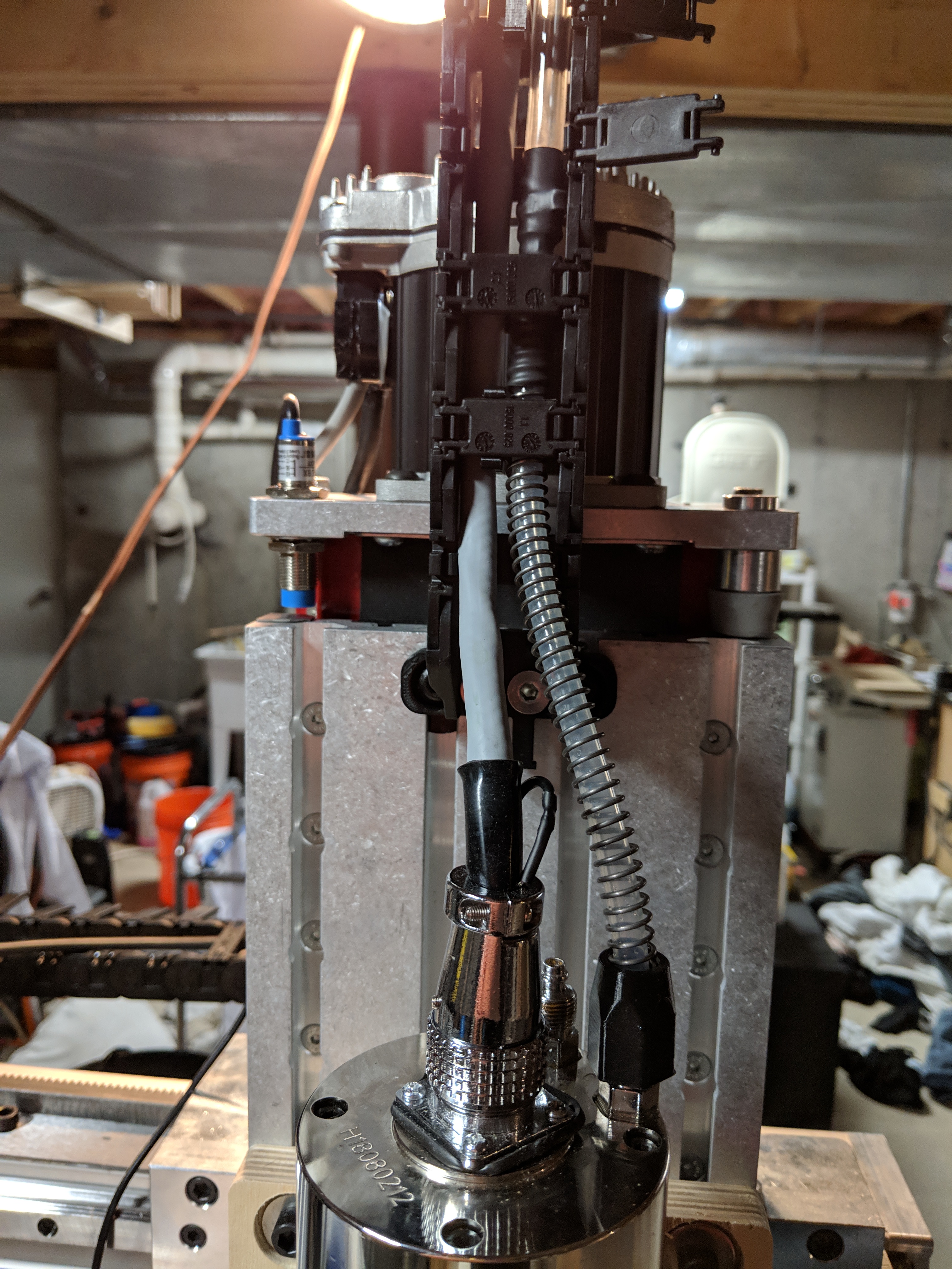
Due to the higher voltages, heat and electrical noise associated with the VFD, I elected to install it in its own box, separate from the rest of the machine control electronics.  The box I ended up with is a pretty tight fit, but I was able to get the VFD, braking resistor, auxiliary cooling fan, and a 30A contactor all in there.  An XLR jack brings in lines from the main control box including power to the 12V fan, 12V to switch the contactor (which switches 240V power to the VFD) and RS-485 for Modbus control (more on that in a future article)

With the ‘rolling chassis’ of my CNC router together, my focus shifted to mounting cable chains on the three axes to support all the wiring.

I ordered all my cable chains from IGUS – they come at a premium price relative to the Chinese cable chains you find on eBay, but you the quality is high and you have a lot of options – width, height, enclosed or open, snap-open on either the inside or outside radius, minimum bend radius, mounting options on either end, internal dividers, and exact length.  The removable slats can pivot open in either direction, and can be easily removed entirely.  They snap in very securely and so far none of them have broken in the process of removal or reinstallation.

X and Z cable chains mountedThe X cable chain is naturally the longest, and I also didn’t want it to be able to sag down below the bottom of the gantry, where it might catch on something while the machine is running.  I mounted it at either end using simple brackets that I welded up from steel angle iron and U-channel.  I later ended up switching to a piece of 1515 extrusion for the end that mounts to the gantry (see later photos).  Pictured here, there is a small L bracket which supports the chain mid-span, but for a more robust solution I subsequently added a sheet metal tray that provides better support.  I also elected to flip the X cable chain around the other way relative to the first photo, so that I could install the control box(es) on the right-hand side of the machine.

X cable chain support trayThe support tray is simply thin sheet metal, bent into a channel shape using a bending brake, painted black and mounted using some off-the-shelf steel L-brackets (redrilled to match the T-slots in the extrusion)

The Z cable chain needs to be long enough to clear the drive motor (not shown) throughout the full range of motion of the axis.  I found that with the chain flush mounted to the front and back of the Z axis, it rubbed against the motor, so I designed mounting brackets with enough of a standoff and a slight angle to mitigate this.

I used a short length of 1530 extrusion anchor fastened to the riser extrusion to mount the top of the Y cable chain.  While I was at it, I switched the bottom mount of the X chain to a piece of 1515 extrusion for more versatility.  The Y chain is mounted using another 3D-printed adapter bracket, since the mounting holes in the chain end don’t match the width between the T-slots.Y cable chainThe bottom end of the Y cable chain mounts to an assembly made of two pieces of 1530 extrusion, mounted to the underside of the base with standard angle brackets.  This arrangement is strong and adjustable so it was easy to get the chain positioned just right.  
Incidentally, this is the second Y cable chain I tried – the first had an unnecessarily small bend radius, and turned out to be too narrow to comfortably fit all the cables and hoses

IGUS does sell an array of different dividers that can be installed in the cable chains to partition them to keep wiring organized.  I found it a bit confusing to try to spec and order those, and I expect they may have been a bit expensive anyway, so I came up with my own design and 3D printed several dozen of them.3D printed cable chain dividersThese snap onto the slats of the chain – I placed them every 3rd link or so.  These were a tremendous help in achieving clean cable runs, as well as segregating signal lines (sensitive) from power lines (noisy) and the water lines for the spindle. 

  I also 3D printed a number of cable clips that bolt to the frame extrusion and clip shut.  Each of these clips was designed with slots sized specifically for all of the cables/hoses that go through it.

Cable organizerI placed several such clips in various spots across the machine – anywhere that cables needed support.  The nice thing about these being 3D printed is that any time I need to add or change anything, it’s a simple matter to just modify the design and print another.


For all of the Clearpath servo wiring, I elected not to purchase the power and control cables from Teknic – they’re nice, but they come in fixed lengths, so I would end up with a lot of excess cable to deal with.  Instead, I ran SJOOW rubber-jacketed 16/2 power cord for the power wiring, and stranded shielded ethernet cable for the control signal wiring.  In a later post I’ll detail my control electronics, but suffice it to say that the control wiring connects to my breakout board via RJ45 connectors, so I simply bought off-the-shelf ethernet cables, cut them in the middle to length, and terminated that end with the appropriate Molex Mini-Fit Jr connector to go into the servo.

One big plus of the pre-made wiring that Teknic sells is that the connectors have an overmolded strain relief.  I wanted to emulate that, but don’t have any capability for injection molding, so I did some experimentation.  I 3D printed backshells in TPU filament, which is flexible, in two halves (clamshell).  Those get clamped over the back of the connector, with some silicone in there for good measure.  The beauty of using a thermoplastic like this is that with the backshell in place, I simply ran a soldering iron around the seam which sealed the two halves together.  This worked great – the two halves show no signs of pulling apart without being cut. Clearpath servo connector "overmolds"

I had to do some adaptation to connect water lines to the spindle.  The fittings on this (imported) spindle are compression style, meant for 6MM ID tubing.  The barb is rather small, and I was not happy with how secure they were(n’t) when I tried to stuff 1/4″ tubing on there.  I was able to source small enough tubing, but I didn’t like how thin-wall it was.  My solution was to use a short length of that tubing to get out of the spindle, up into the Z cable chain, and then an inline barb fitting adapts it to standard flexible clear 1/4″ ID PVC tubing with a sufficient wall thickness that it’s not so prone to kinking.  I also incorporated a piece of spring stock over the thin-wall silicone tubing to add more resistance to pinching or kinking.

I’m still not completely thrilled with these water line connections – because the tubing is so soft and thin, even with the compression nuts tight it would still be possible to tug the hoses off the barbs.  Someday I will revisit and improve that, but for now it’s held up.

More to follow on the rest of the water cooling loop in a future post…

I decided at the inception of this project that I was going to use brushless servos instead of stepper motors, for all of the usual reasons – better power, speed and no possibility of losing position (skipped steps).  It’s a significant expense, since that class of motors starts at several hundred dollars apiece, but I’m taking the “buy once, cry once” approach on this.

There are two main contenders in the market that I’m personally aware of – Teknic and DMM Tech.  My inspiration to use servos started from videos from NYC CNC and other youtube channels, showcasing the performance of Teknic’s Clearpath SDSK servos – so to be honest, I didn’t really even give DMM Tech a second thought.  In fairness, on paper they do appear to offer very competitive motors, with potentially more power and positioning resolution for the money.  Still, the clearpath motor offerings more than cover my needs, and the approachability of the Teknic website, documentation and configuration software, and the ironclad return policy, all really helped lower the barrier to entry for me as a hobbyist.

(Note: I’m not in any way affiliated with Teknic – just a satisfied customer)

The range of Clearpath motors is broad – spanning different frame sizes (NEMA 23, NEMA 34, and on up), different motor body sizes within each frame size, and for any given size you can select from motors wound for higher speed, or higher torque, or somewhere in between.  Not being a mechanical engineer, or having firm requirements for the machine performance, my analysis was crude at best, but I settled on the following criteria:

  1. NEMA 34 – the CNCRP pro-series rack & pinion drive system accommodates either NEMA 23 or 34 motors, however it became immediately apparent that the moderately higher cost of NEMA 34 servos is well- justified by substantially higher performance.
  2. Capable of 1000+ IPM – I have no illusions about cutting most materials at anywhere near this high a feedrate, but I want to have the ability to run it fast during rapids, and for 3D surfacing operations.  The CNCRP pro-series rack & pinion drive system drive ratio works out to close to 1 IPM per RPM, so meeting this criteria was practically a given – but it did raise the question of whether I would want to go even faster…
  3. Sub-0.001″ positioning resolution – understanding that this machine is not going to compete with an actual CNC mill for accuracy, I still wanted reasonable resolution to make the most of it.  Given the high drive ratio of the rack & pinion drives, this meant going with the enhanced precision option on motors, which puts them at a control resolution of 12800 counts per revolution.

This narrowed down my selection quite a bit, but I still needed to decide whether to go with a model biased for maximum torque (such as the CPM-SDSK-3421S-ELN), or more of a speed vs. torque compromise (such as the CPM-SDSK-3421P-ELN).  Not having the experience to settle it with a mechanical analysis, I took advantage of the Teknic guarantee and picked up a 3421P to test out – with which I did the following pseudoscientific test, running the motor on my partially-assembled X axis with a representative weight (35lb) attached to emulate the Z axis and spindle.  

1250 IPM reflects what the 3421S-ELN is capable of, while 3000 IPM is the limit of the 3421P-ELN I was testing.  Long story short, while seeing it throw that weight around at 3000 IPM was seriously impressive, it seemed like serious overkill for how I would reasonably expect to run the machine.  More importantly though, I took a closer look at acceleration.  Consider that at very high rapids rates, it can take quite some distance to accelerate and decelerate – so for relatively short moves, on the order of a few inches, the machine may never even reach max velocity.  So for toolpaths without a lot of very long rapids moves, a higher-torque motor (capable of higher acceleration) can outperform one with higher max speed.  

Conveniently, the interface software for Clearpath servos allows you to get a very good look into the performance of the motor in your real application, by allowing capture of parameters like torque, velocity and position error, plotting them on an oscilloscope-like display along with fault indications.  This made it easy to put the motor through its paces and look at how much margin it had.  

As an example, here’s the 3421P during two 10 inch moves (back and forth) at 1G acceleration, 1250 IPM max velocity.  The blue trace is velocity, red is torque (scale = +/- 100% of max rated), and dark green is position error (scale = +/- 64 encoder counts)


 Suffice it to say that when pushed to 3000 IPM, I had to dial back acceleration to around 0.4G to keep position tracking reliably in range.   At that acceleration rate, it took a move longer than a foot to even hit max velocity – which means that in real toolpaths, at least for the kinds of things I usually make, it would never get there.  This was enough to make up my mind – Teknic gladly RMA’ed the motor and exchanged it for the lower-speed, higher-torque 3421S.

With the new motor in hand, I resumed testing.  Here it is at 1000 IPM, 1G acceleration, +/- 10″ rapids moves.  Torque is not even close to saturating, position tracking error is well within range, and at these rates the max velocity is reached for moves as short as roughly 3 inches. 

For a slightly more representative test, I ran it through a simple 2D adaptive toolpath, with only the X axis connected (Mach4 didn’t need to know that the other axes didn’t exist)

At that point, it was readily apparent that the machine needed to be on a really solid base – because that level of acceleration can be fairly violent.  At the time, the machine was still sitting on sawhorses – and through the course of the above testing the whole thing walked some distance across the floor.  So began the construction of a proper base – which I’ll cover in the next post.

This lengthy post captures the machining of the 8 (or so) major parts for this CNC router project, spanning 4-6 months of incremental progress.

The real crux of building my new CNC router was the capability to machine the numerous custom aluminum plates that hold everything together.  If I couldn’t make those myself and had to shop them out instead, then the total cost of the build would have become unreasonable, and it wouldn’t have been nearly as much of a learning experience.

Fortunately, my local makerspace (MakeIt Labs) has a Tormach PCNC 1100 mill, and happened to run a training/certification course at the right time.  This capability really made the project possible.

The XY working area of the Tormach is 18″x9.5″, which was a bit of a restriction for some of the plates I needed to make.  None were over 12″ wide, but the necessary lead-in and lead-out for a fly cutter still means that one has to be relatively careful in positioning the setup.  The Y limit was more restrictive, and I had to limit 3 of my plates to about 8″ in one dimension to accommodate.  

I started with the four plates which join the X axis with the risers that connect it to the Y axis, each of which is around 3″x6″.  These were relatively straightforward rectangular parts with simple features (counterbored holes, mostly):

These went according to plan:

And I was soon able to assemble the first few parts of the machine.   

For aesthetic reasons, I wanted all of my larger plates to have the entire outer profile cut on the mill, which made for a workholding challenge.  I considered making fixture plates to bolt the workpiece in place between setups, but since I had a bunch of different parts to make, I decided to first try out the tape + superglue method advocated by NYC CNC.

Long story short, it worked as well as I could have hoped.  I made a general-purpose plate by bolting down a scrap piece of corian, surfacing a large rectangle and adding some pockets in the corner for prying – which proved to be critical.  On the part pictured above, I had to pause and run out to an auto parts store and buy a proper pry bar – the tape held so well (with that much surface area) that screwdrivers couldn’t budge it without snapping.

The above part is what I refer to as the “X carriage plate” which is rather central to the machine, tying the X and Z axes together, and is also the single largest machined part – and therefore the most strain on the limited XY working area of the Tormach.  

Like most of the plates in this design, this one needed features machined on both sides, so I had to do a second setup.  Since I finished the outer profile in the first setup, this one was easy enough to put on top of the vise, with jaws flipped. 

The operations on the top face are pretty simple – face, pocket the counterbores, and chamfer everything.  Since I set up my drilling ops in the first setup to not quite break through (being kind to my fixture plate), the combination of facing off 0.010″ or so and then giving everything a generous chamfer was enough to complete all the through holes running down the center.

At a later date, I ended up putting the X Carriage plate back into the Tormach to add some extra mounting holes on either side to facilitate attaching accessories (such as a dust boot) in the future.  Since I don’t yet have said accessories designed, I went with an array, totaling 20 threaded holes.  This would have been tedious to hand tap, so I used the opportunity to try out thread milling, using a 1/4-20 multi-form thread mill from Lakeshore Carbide.  It went exceedingly well, after running a handful of test holes in a scrap piece of aluminum first.  This operation relies on interpolating the hole to get the right diameter, so it’s naturally susceptible to the backlash of the machine – I spent about 10 minutes dialing in the right diameter offset via guess-and-check on the test piece, after which I was able to sail through drilling and tapping all 20 holes on the real plate with no issues. X Carriage plate with accessory mounting holes added

Next up was the smaller plate that bolts onto the top edge of the X carriage plate and holds the drive assembly for the X axis:

This was the first notable departure from the design of the CNCRP Pro series machine.  In that design, the plate is much larger, surrounding the drive pinion, and the teeth of the rack face the front of the machine – so the drive pinion is pulled toward the rear by the tensioner.  I spun the tensioner around to the top of the X carriage, flipping the rack front to back, and as a result this plate needs to support nothing more than the shoulder bolt which serves as the pivot for the drive assembly – as well as some convenient mounting holes for later use – which means that it can be much smaller.

This was the first (of several) plates which had a very non-rectangular profile, and thus required some more thought to machine.  It’s 3/4″ thick (like all my plates) and I wanted to avoid having to cut it out by deep slotting.  What I settled on was to do a 2D adaptive operation to cut a wide slot around the perimeter, as a compromise between slotting versus machining away 100% of the waste material starting at the outer perimeter of the stock.  

This is not a fast toolpath.  Cutting that long, meandering slot by tiny, scalloped adaptive cuts is pretty slow – but the Tormach’s meager flood coolant was able to wash the chips out the slot fast enough, and it presented minimal stress to the tool, machine and workpiece.  As an added bonus, it sounds rather like a warning klaxon…

The reason the adaptive portion of the toolpath stops short of breaking through on the right-hand edge is due to a lesson learned – when it first breaks through, that cyclical adaptive movement is prone to catching on the sharp edge of the waste piece.  Stopping just shy of breaking through, and finishing with a gentle profile cut (shallow step-down) proved to behave much better.

That bracket also required holes on the long edge (for dowel pins and mounting bolts) and the opposite edge, neither of which was done yet in the above photo – but suffice it to say those were straightforward to do in the vise.

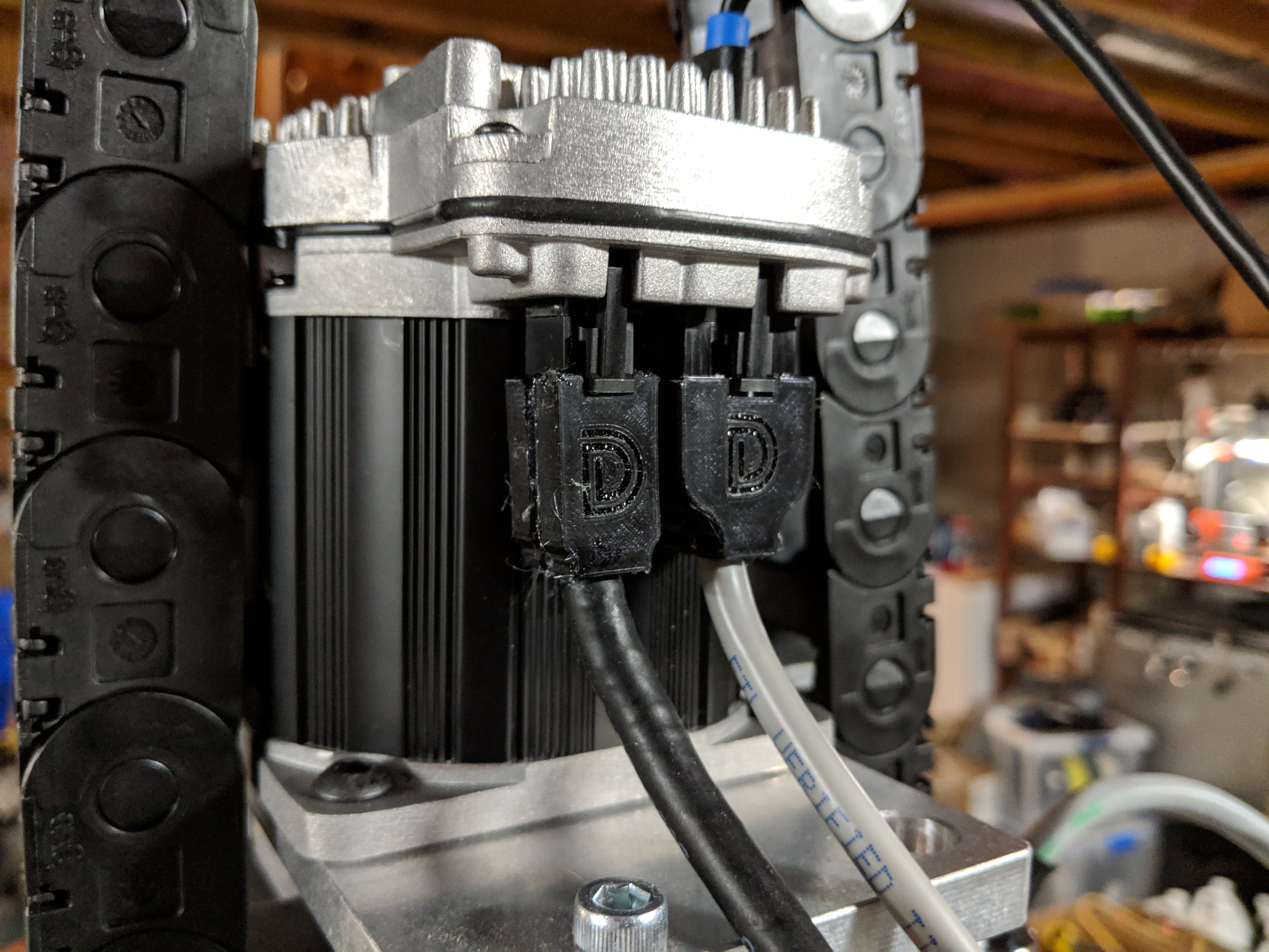
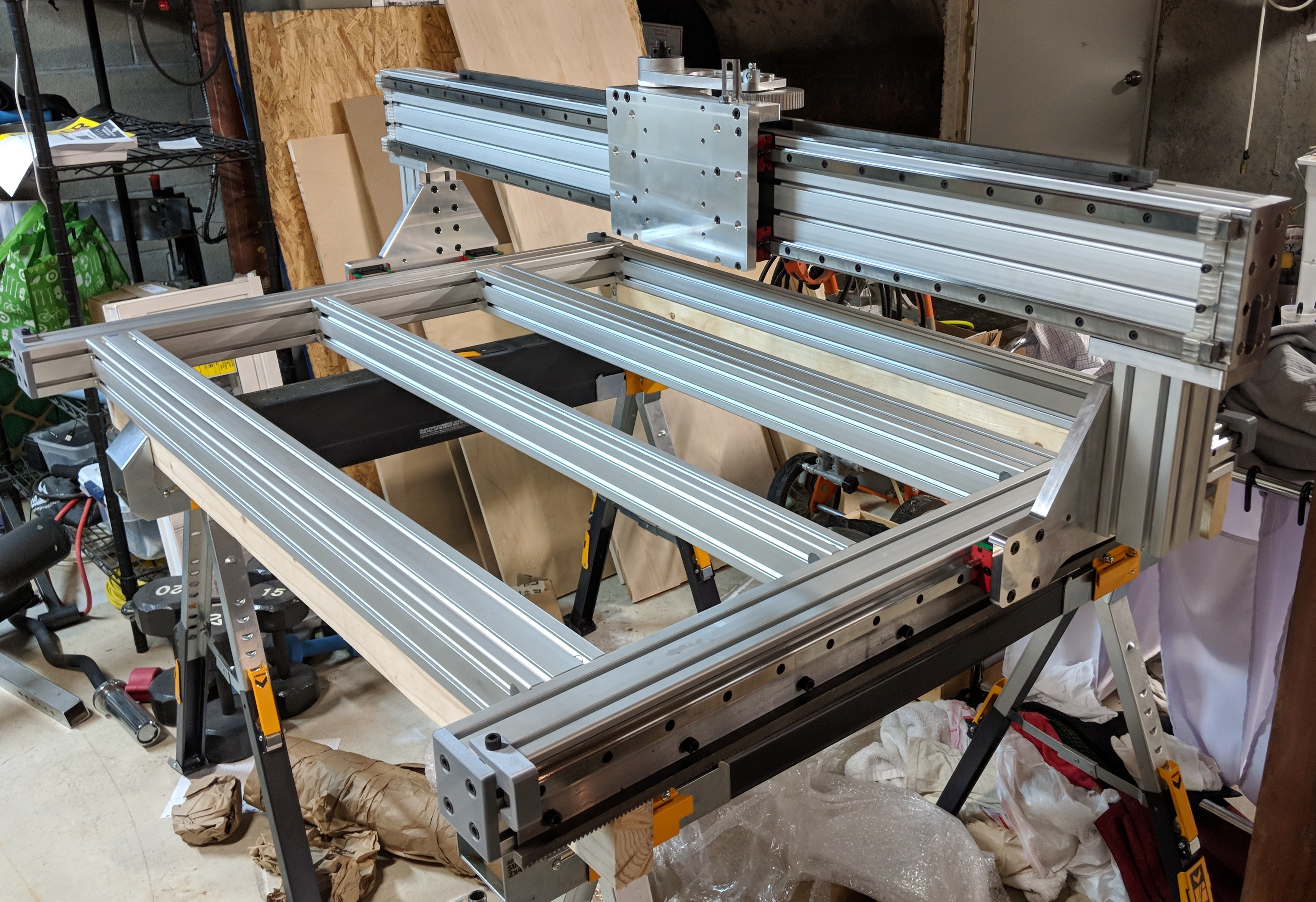
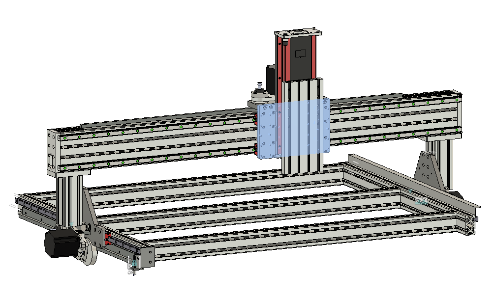
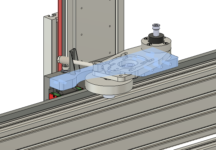
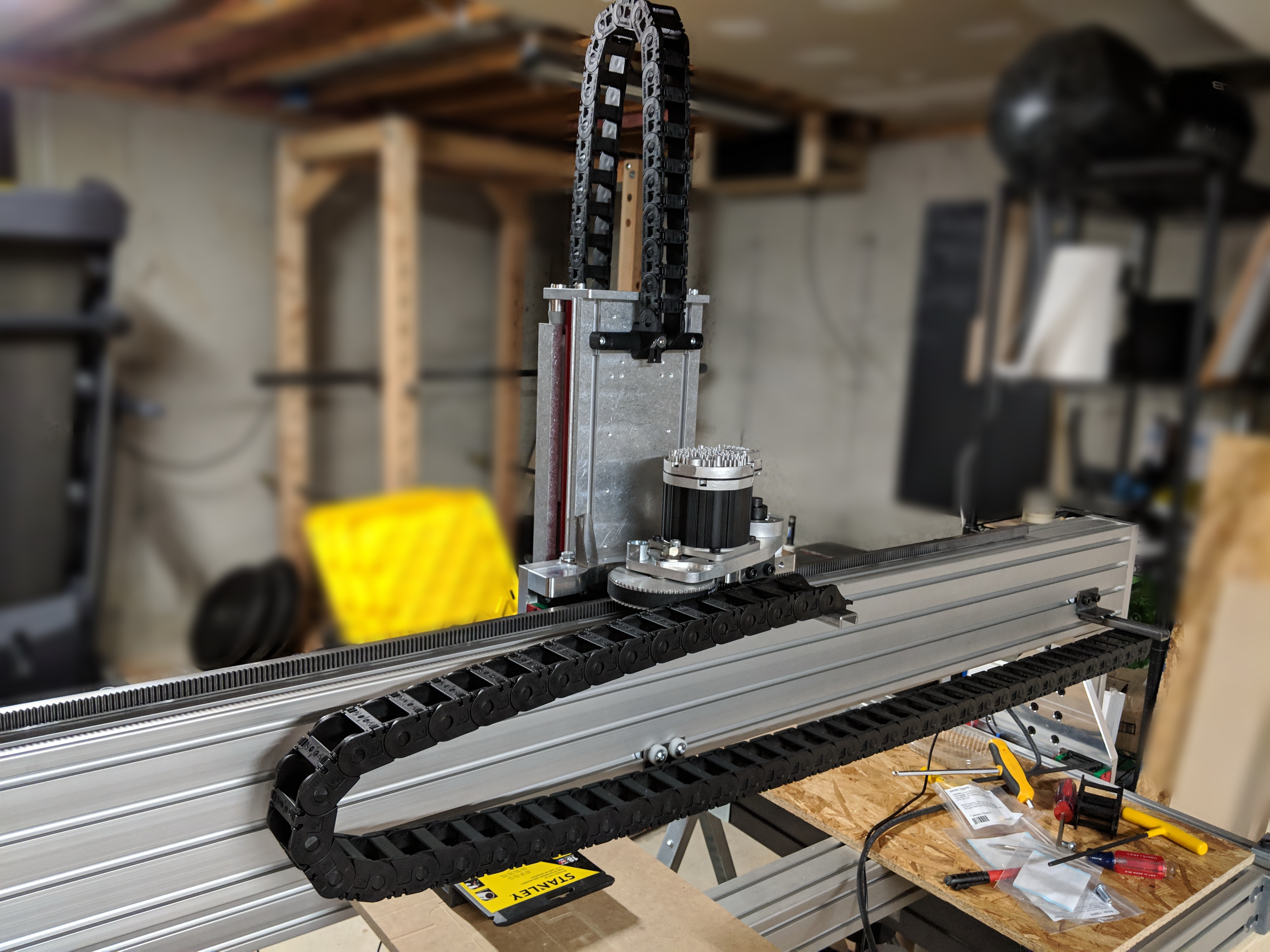
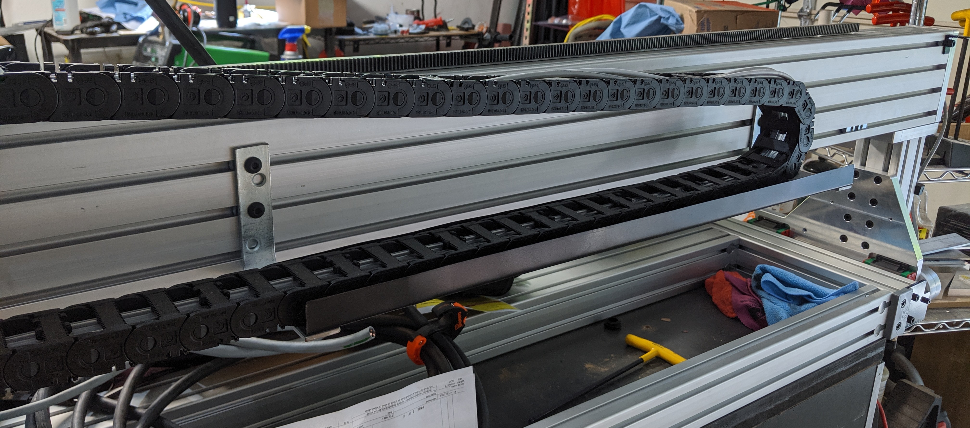
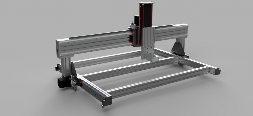
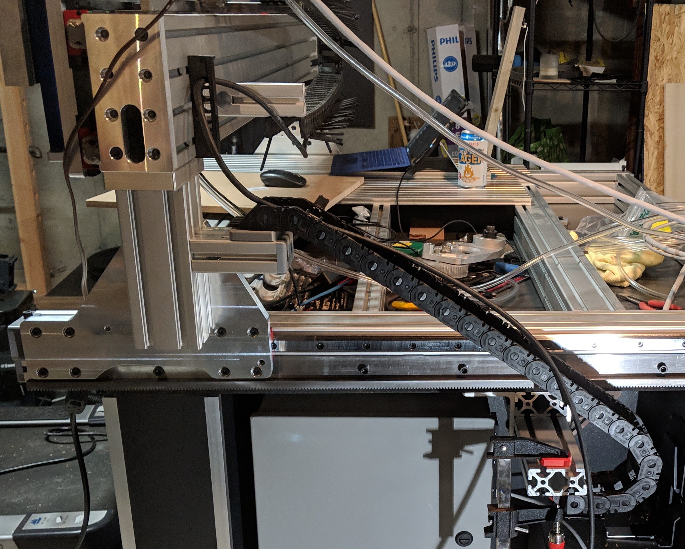
At this point, I was able to mostly assemble the gantry
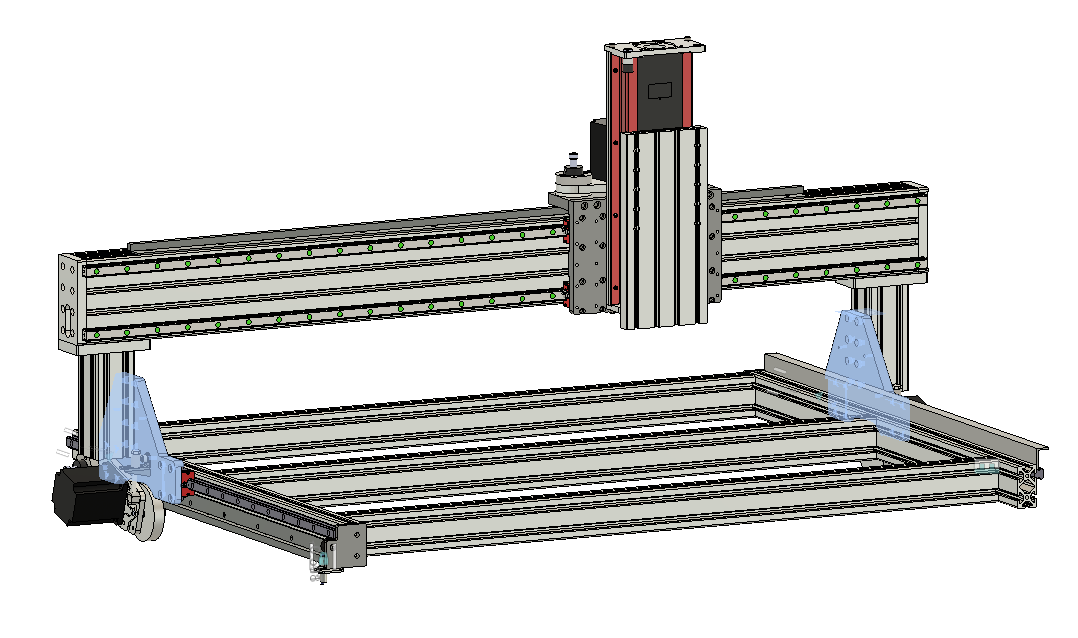
, checking the fit of the 6 machined parts up to this point.

The last major machined parts for the CNC router were the riser plates, which connect the entire gantry assembly to the Y-axis linear guides on either side of the base.

Like the X carriage plate, the design of these parts was constrained by the working area of the Tormach – most importantly, this limited them to about 8 inches in height, whereas it would have been preferable to bring them all the way up to the bottom of the gantry.  The two other major design constraints were to eliminate any possibility of interference between the Z axis and spindle, and to squeeze in the drive assembly (requiring a pivot point) while maximizing the size of the vertical 3030 extrusion which attaches to the riser plate.  

These plates were sort of the culmination of all the lessons learned up to that point, since they shared the challenges of the previous two parts – large size and non-rectangular profile.  As such, the first side was done with the blue-tape method and went as smoothly as could be expected. 

The second side was more complicated because there’s no way to hold it in the Tormach vise with hardjaws.  This side only required counterbores and a cosmetic chamfer, so it was tempting to just buy a piloted counterbore bit and try to do those freehand on the drill press.  In the end, I elected to suck it up and make a softjaw.  Since the left and right plates are mirror images of each other, but the curved region at the bottom of the plate is asymmetric front-to-back, I couldn’t use a single softjaw for both plates – but fortunately, the Monster Jaw softjaw blanks I used are able to be used double-sided, so I was able to mirror the profile on either side.

At long last, the completion of the riser plates allowed the whole ‘rolling chassis’ of the CNC router to be assembled – a huge milestone for the project!

This concludes the build of the basic chassis of the machine.  The fabrication of many additional unique parts is yet to come, and this wasn’t the last time that most of these particular machined parts saw the Tormach – stay tuned.

The project of building my new, bigger, better CNC router is well underway at this point, so I’ll begin with a recap of how it started.

I started with CNC by building an X-Carve in 2017.  I was determined to have a working area large enough for the biggest item I could envision myself reasonably wanting to make that warranted the use of CNC, which at the time was plywood panels for kitchen cabinet carcasses.  That pushed me beyond the limits of the machine sizes available in complete kit form, but Inventables offers their makerslide rail up to a length of 1800mm, and they were willing to work with me to buy just the parts I needed to ultimately build a 1000x1500mm machine, without ending up with any unnecessary pieces.

Over the course of about a year, I built, upgraded, and learned a lot.   I raised the Y rails and added mid-span supports, put it on a torsion box base, made wasteboards with threaded inserts and dog holes for clamps, upgraded to larger steppers, added dust shields, swapped in a greatly improved Z-axis, upgraded the belts to 9mm 3GT, built a complete dust shoe solution, and switched to GeckoDrive stepper drivers with an Ethernet SmoothStepper and Mach4 for control.

My X-Carve in its near-final state

I was able to make a lot of great things with it throughout that time, but I can’t help but strive for continual improvement – to me, the machine itself has been the hobby all along, more so than using it to make things.  By that point, however, it was becoming obvious that I was reaching the limits of the basic chassis design of the X-Carve – there’s only just so far you can take it given the size of the X and Y rail extrusions.  It’s just physics.  

So, I started looking around at the next higher tier of CNC routers on the market.  The options in this range are far fewer than you find in the sub-$2k range, so this search very quickly narrowed down to Fineline Automation’s Saturn Series, CNC Router Parts’ Standard Series and also their Pro Series.

Really, all of them look to be very solid machines, but the Saturn Series was initially my first choice.  For the money, the welded steel frame is a big deal, and the overall construction appears to be very solid.  I was a bit put off, however, that the 4’x4′ model was of the new and improved “Saturn 2” series, with a number of big improvements advertised – but the smaller 2’x4′ model is still the original design.  Furthermore, from what I saw on various forums, Fineline seems to have a reputation for long lead times and lack of communication.  This was reinforced for me when they never responded to any of my inquiries, despite the fact that I was just about ready to pull the trigger on a machine.  For better or worse, that was enough for me to write them off.

It was around that time period when I had the opportunity to get trained and certified on the Tormach PCNC 1100 CNC mill at my local Makerspace, which really opened up my options for fabrication.  Looking at the design of the CNCRP Pro Series, it became evident that most of the parts for such a machine were within the capabilities of the machine(s) I now had available to me.  I went through the exercise of tabulating the projected material costs to build one – it told me that I could stand to save a bit under $1K relative to the price of their kit.  However, I know full well that the unexpected incidental expenses always add up, so by the time all is said and done I am sure it will come out to a wash at best, especially if I place any value at all on my own time.  But – that’s not the point.  The experience of designing, machining and building such a major project was extremely appealing to me both as a learning experience and as an accomplishment.

Of course, there were also some design details that I was interested in changing.  Not very many, mind you – I really found little to no fault in any aspect of the CNCRP machine design.  The main thing was that I wanted to be able to clamp stock vertically on the front edge, for doing wood joinery such as box or dovetail joints – this required extending the Y axis out past the front edge of the work area by a few inches, also making it longer overall so as to maintain a full 2’x4′ working area over the wasteboard.  Also, less importantly, I wanted to use imperial extrusions rather than metric, so I could get away from having to collect so much metric hardware and tooling.  Overall, I just wanted to make it my own, if in subtle ways.

Thus began the long process of designing the machine in Fusion 360.  Such a large design was good practice in using the software, and it was all a good exercise in Design for Manufacturing (DFM) since each machined part needed to fit within the ~9″x16″ working volume of the Tormach 1100 that I would be using and be reasonable to machine without requiring an excess of fixtures or other complicated or specialized setups.

CNC Router model - 3D render
CNC Router model – 3D render

And this is where it ended up, more or less:I’ve made some subtle changes to the assembly that didn’t affect the machined parts and therefore I didn’t bother updating the model, but this is pretty close to the final design.

Stay tuned for the next installment, where the build begins…