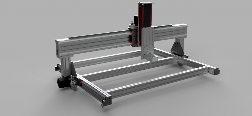
This lengthy post captures the machining of the 8 (or so) major parts for this CNC router project, spanning 4-6 months of incremental progress.

The real crux of building my new CNC router was the capability to machine the numerous custom aluminum plates that hold everything together. If I couldn’t make those myself and had to shop them out instead, then the total cost of the build would have become unreasonable, and it wouldn’t have been nearly as much of a learning experience.
Fortunately, my local makerspace (MakeIt Labs) has a Tormach PCNC 1100 mill, and happened to run a training/certification course at the right time. This capability really made the project possible.
The XY working area of the Tormach is 18″x9.5″, which was a bit of a restriction for some of the plates I needed to make. None were over 12″ wide, but the necessary lead-in and lead-out for a fly cutter still means that one has to be relatively careful in positioning the setup. The Y limit was more restrictive, and I had to limit 3 of my plates to about 8″ in one dimension to accommodate.
I started with the four plates which join the X axis with the risers that connect it to the Y axis, each of which is around 3″x6″. These were relatively straightforward rectangular parts with simple features (counterbored holes, mostly):
These went according to plan:

And I was soon able to assemble the first few parts of the machine. 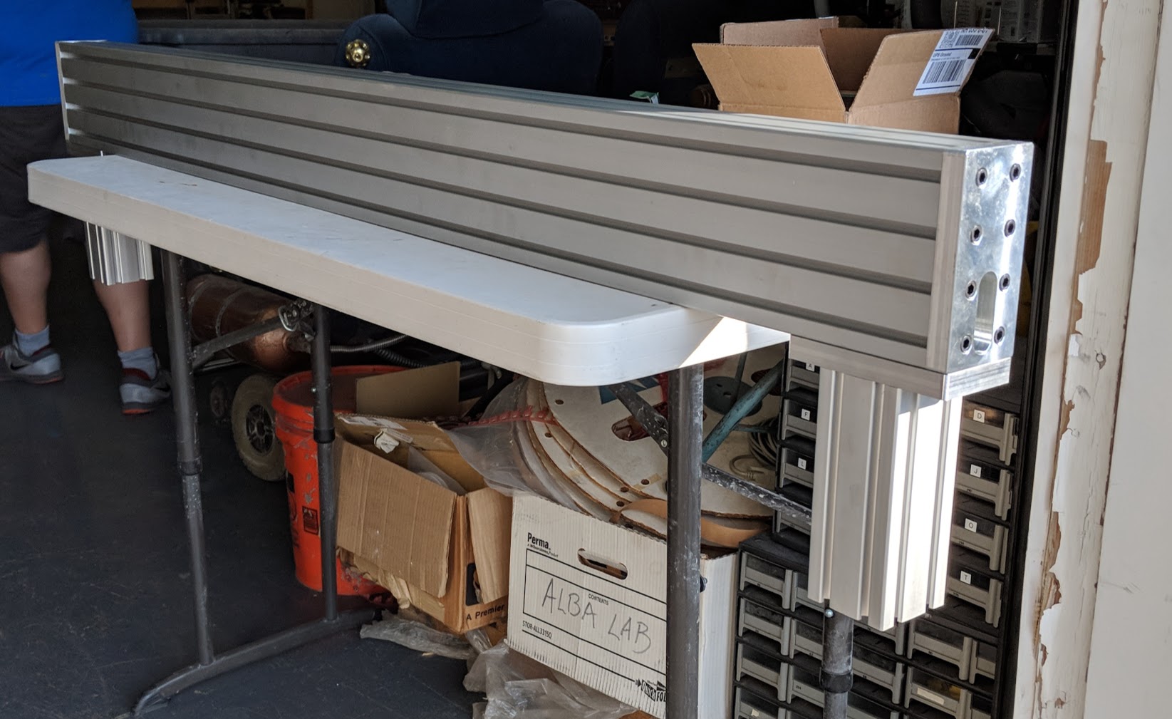
For aesthetic reasons, I wanted all of my larger plates to have the entire outer profile cut on the mill, which made for a workholding challenge. I considered making fixture plates to bolt the workpiece in place between setups, but since I had a bunch of different parts to make, I decided to first try out the tape + superglue method advocated by NYC CNC.
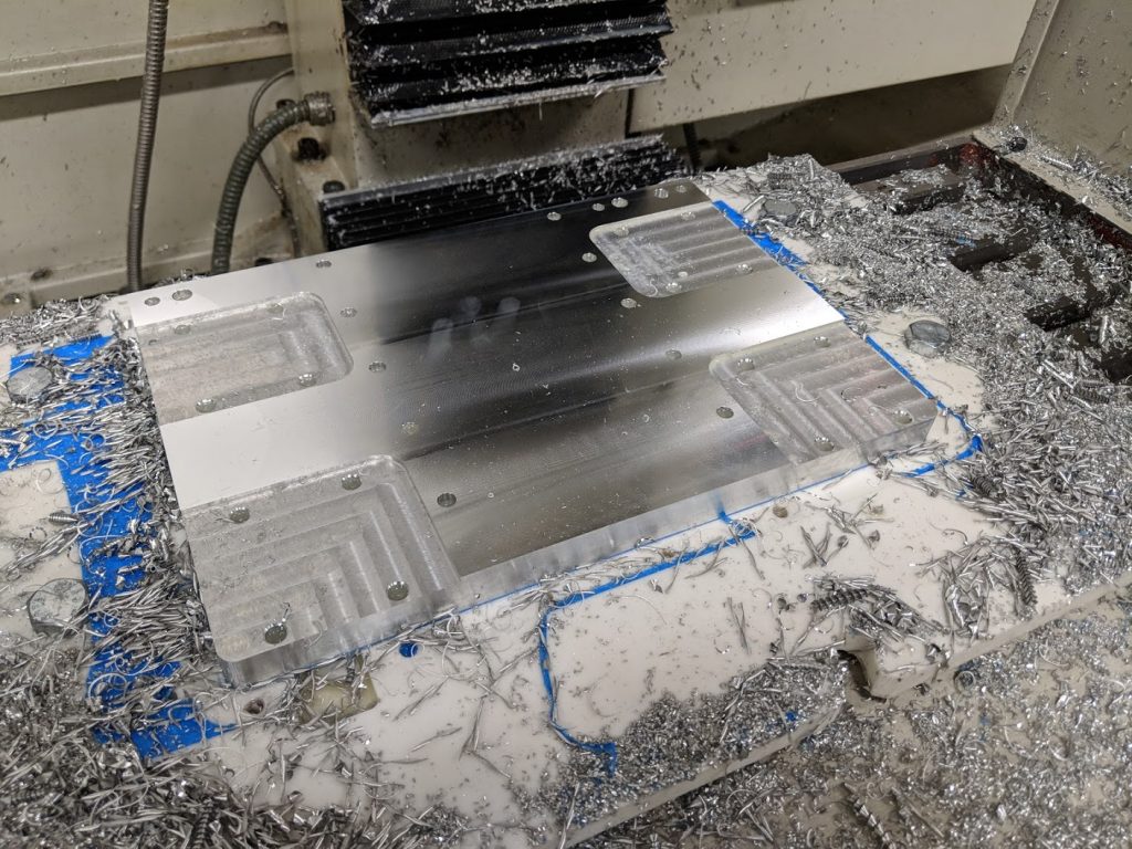
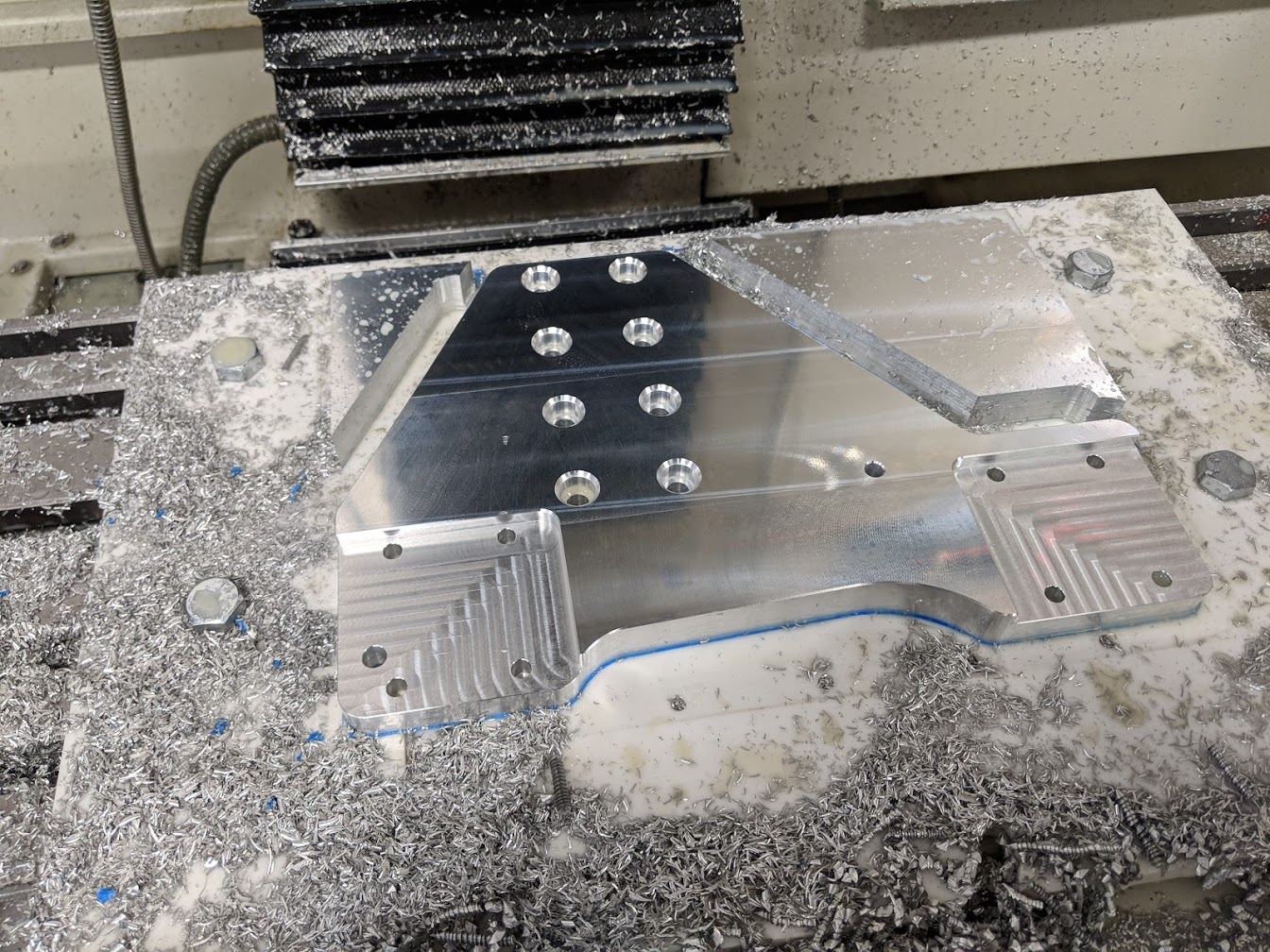
Long story short, it worked as well as I could have hoped. I made a general-purpose plate by bolting down a scrap piece of corian, surfacing a large rectangle and adding some pockets in the corner for prying – which proved to be critical. On the part pictured above, I had to pause and run out to an auto parts store and buy a proper pry bar – the tape held so well (with that much surface area) that screwdrivers couldn’t budge it without snapping.
The above part is what I refer to as the “X carriage plate” which is rather central to the machine, tying the X and Z axes together, and is also the single largest machined part – and therefore the most strain on the limited XY working area of the Tormach. 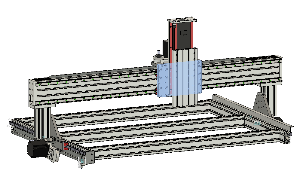
Like most of the plates in this design, this one needed features machined on both sides, so I had to do a second setup. Since I finished the outer profile in the first setup, this one was easy enough to put on top of the vise, with jaws flipped.
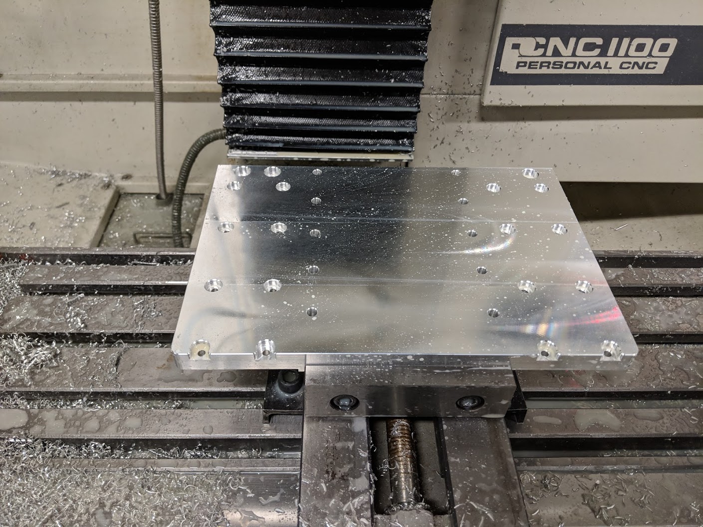 The operations on the top face are pretty simple – face, pocket the counterbores, and chamfer everything. Since I set up my drilling ops in the first setup to not quite break through (being kind to my fixture plate), the combination of facing off 0.010″ or so and then giving everything a generous chamfer was enough to complete all the through holes running down the center.
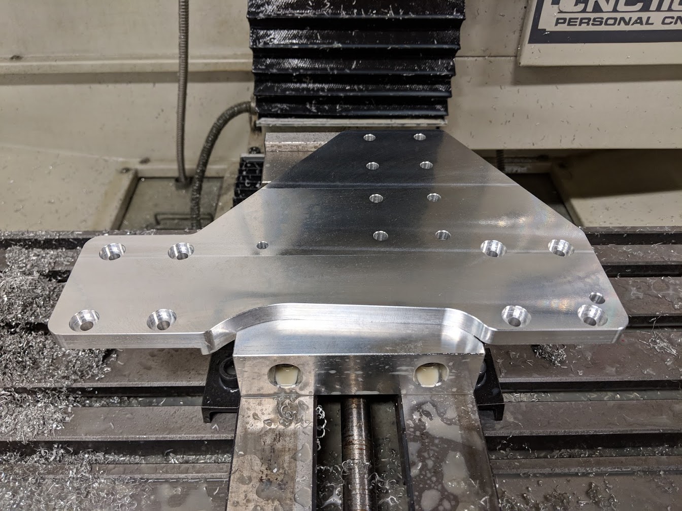
At a later date, I ended up putting the X Carriage plate back into the Tormach to add some extra mounting holes on either side to facilitate attaching accessories (such as a dust boot) in the future. Since I don’t yet have said accessories designed, I went with an array, totaling 20 threaded holes. This would have been tedious to hand tap, so I used the opportunity to try out thread milling, using a 1/4-20 multi-form thread mill from Lakeshore Carbide. It went exceedingly well, after running a handful of test holes in a scrap piece of aluminum first. This operation relies on interpolating the hole to get the right diameter, so it’s naturally susceptible to the backlash of the machine – I spent about 10 minutes dialing in the right diameter offset via guess-and-check on the test piece, after which I was able to sail through drilling and tapping all 20 holes on the real plate with no issues. 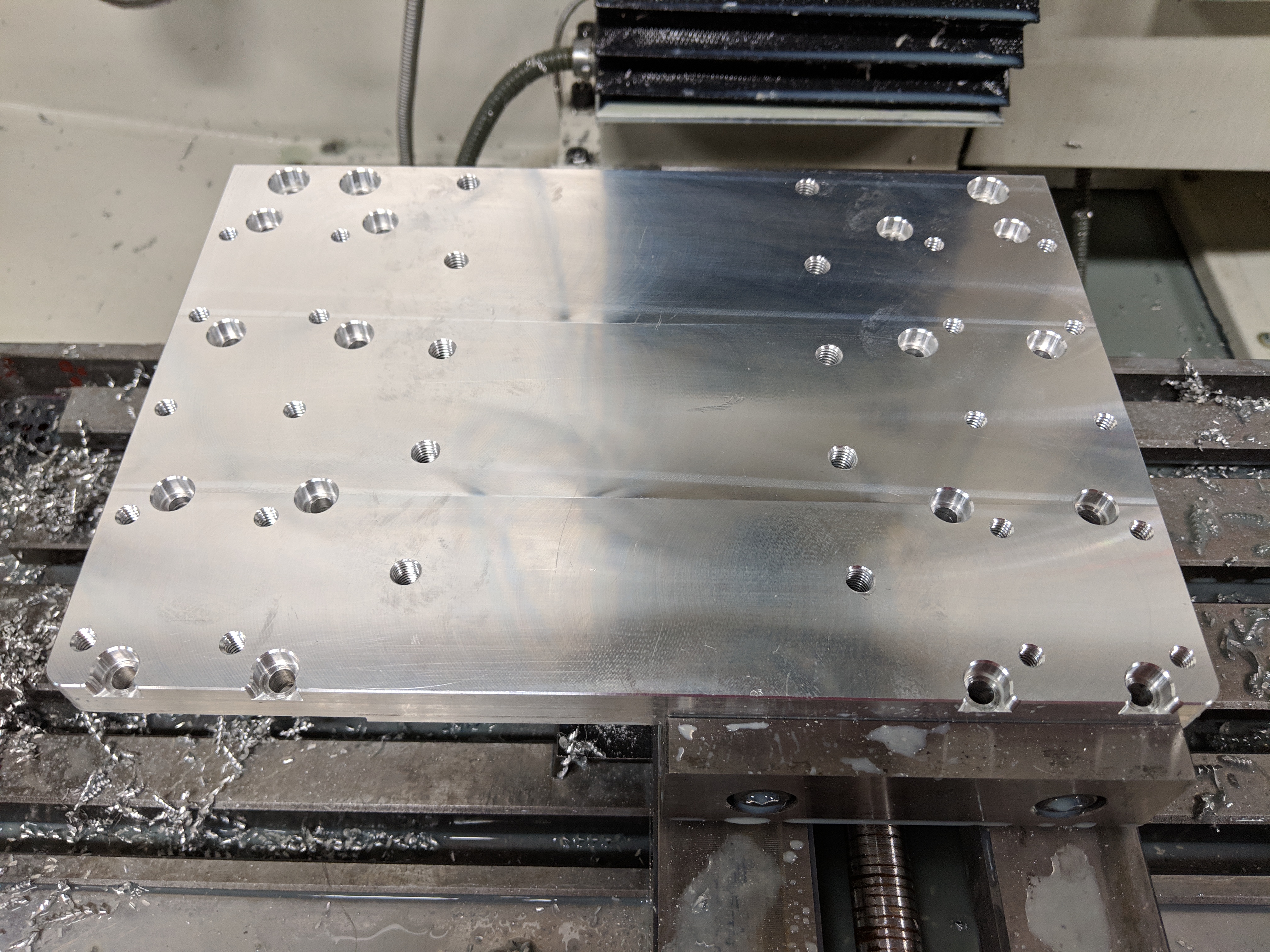
Next up was the smaller plate that bolts onto the top edge of the X carriage plate and holds the drive assembly for the X axis: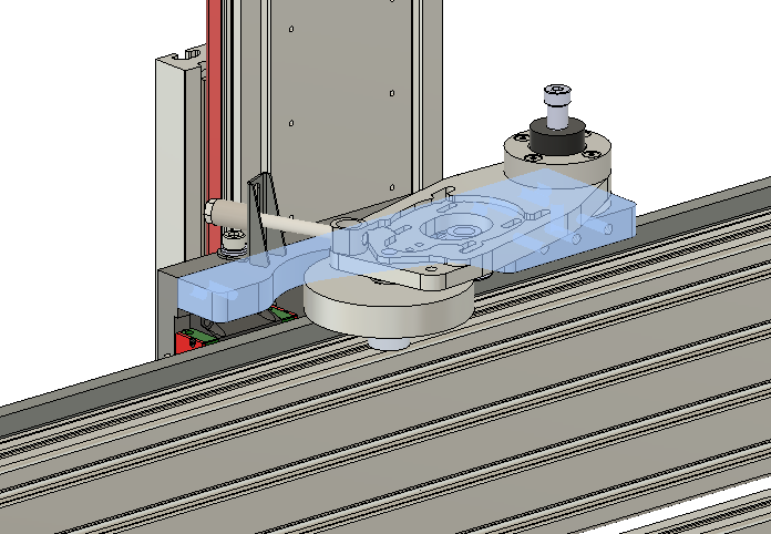
This was the first notable departure from the design of the CNCRP Pro series machine. In that design, the plate is much larger, surrounding the drive pinion, and the teeth of the rack face the front of the machine – so the drive pinion is pulled toward the rear by the tensioner. I spun the tensioner around to the top of the X carriage, flipping the rack front to back, and as a result this plate needs to support nothing more than the shoulder bolt which serves as the pivot for the drive assembly – as well as some convenient mounting holes for later use – which means that it can be much smaller.
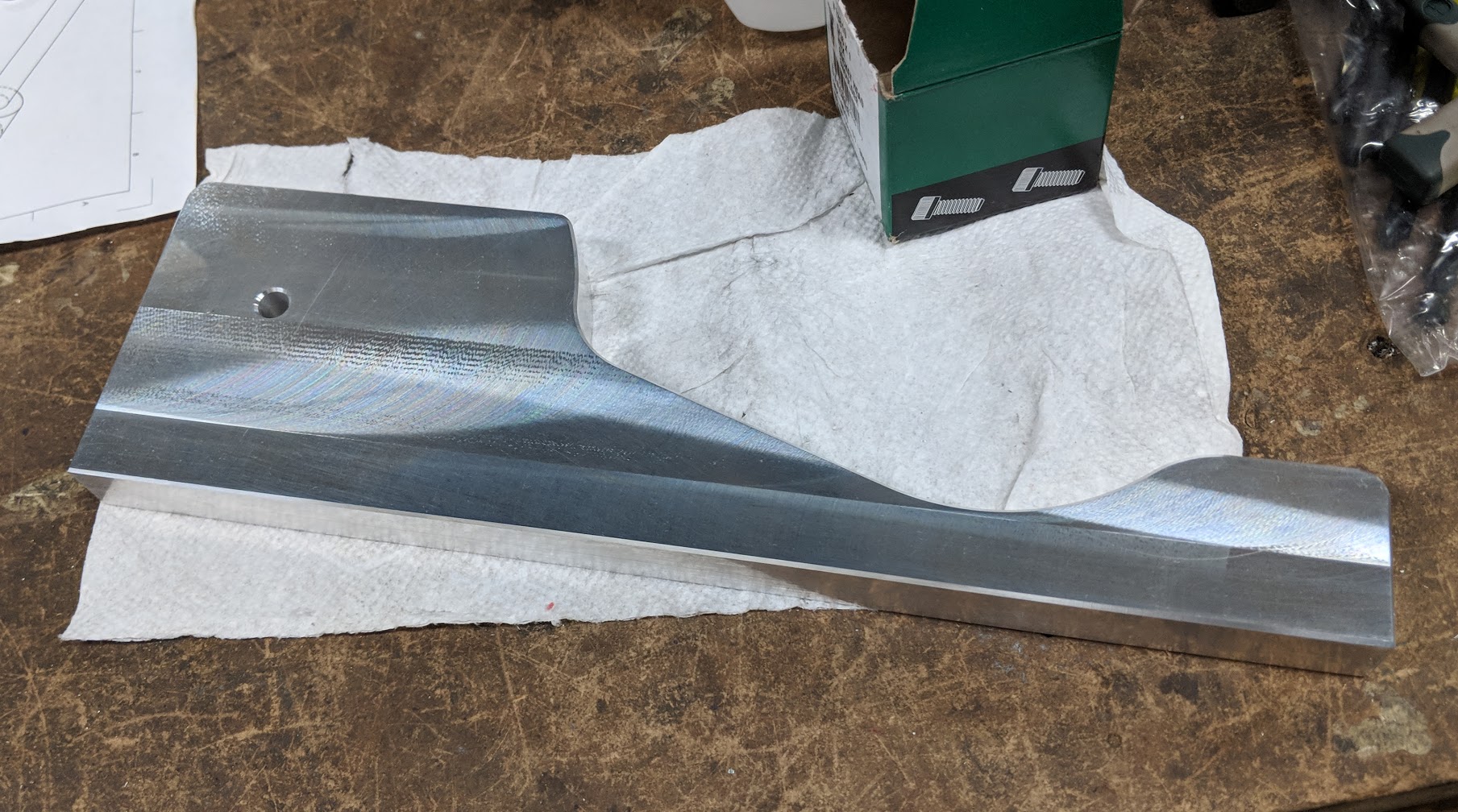
This was the first (of several) plates which had a very non-rectangular profile, and thus required some more thought to machine. It’s 3/4″ thick (like all my plates) and I wanted to avoid having to cut it out by deep slotting. What I settled on was to do a 2D adaptive operation to cut a wide slot around the perimeter, as a compromise between slotting versus machining away 100% of the waste material starting at the outer perimeter of the stock. 
This is not a fast toolpath. Cutting that long, meandering slot by tiny, scalloped adaptive cuts is pretty slow – but the Tormach’s meager flood coolant was able to wash the chips out the slot fast enough, and it presented minimal stress to the tool, machine and workpiece. As an added bonus, it sounds rather like a warning klaxon…
The reason the adaptive portion of the toolpath stops short of breaking through on the right-hand edge is due to a lesson learned – when it first breaks through, that cyclical adaptive movement is prone to catching on the sharp edge of the waste piece. Stopping just shy of breaking through, and finishing with a gentle profile cut (shallow step-down) proved to behave much better.
That bracket also required holes on the long edge (for dowel pins and mounting bolts) and the opposite edge, neither of which was done yet in the above photo – but suffice it to say those were straightforward to do in the vise.
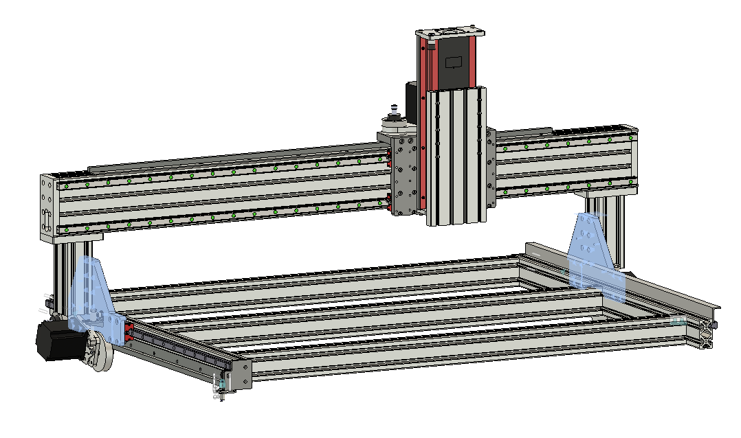
 At this point, I was able to mostly assemble the gantry, checking the fit of the 6 machined parts up to this point.
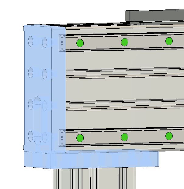
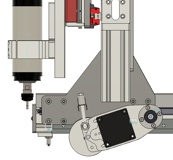
The last major machined parts for the CNC router were the riser plates, which connect the entire gantry assembly to the Y-axis linear guides on either side of the base.
Like the X carriage plate, the design of these parts was constrained by the working area of the Tormach – most importantly, this limited them to about 8 inches in height, whereas it would have been preferable to bring them all the way up to the bottom of the gantry. The two other major design constraints were to eliminate any possibility of interference between the Z axis and spindle, and to squeeze in the drive assembly (requiring a pivot point) while maximizing the size of the vertical 3030 extrusion which attaches to the riser plate.
These plates were sort of the culmination of all the lessons learned up to that point, since they shared the challenges of the previous two parts – large size and non-rectangular profile. As such, the first side was done with the blue-tape method and went as smoothly as could be expected.
The second side was more complicated because there’s no way to hold it in the Tormach vise with hardjaws. This side only required counterbores and a cosmetic chamfer, so it was tempting to just buy a piloted counterbore bit and try to do those freehand on the drill press. In the end, I elected to suck it up and make a softjaw. Since the left and right plates are mirror images of each other, but the curved region at the bottom of the plate is asymmetric front-to-back, I couldn’t use a single softjaw for both plates – but fortunately, the Monster Jaw softjaw blanks I used are able to be used double-sided, so I was able to mirror the profile on either side.
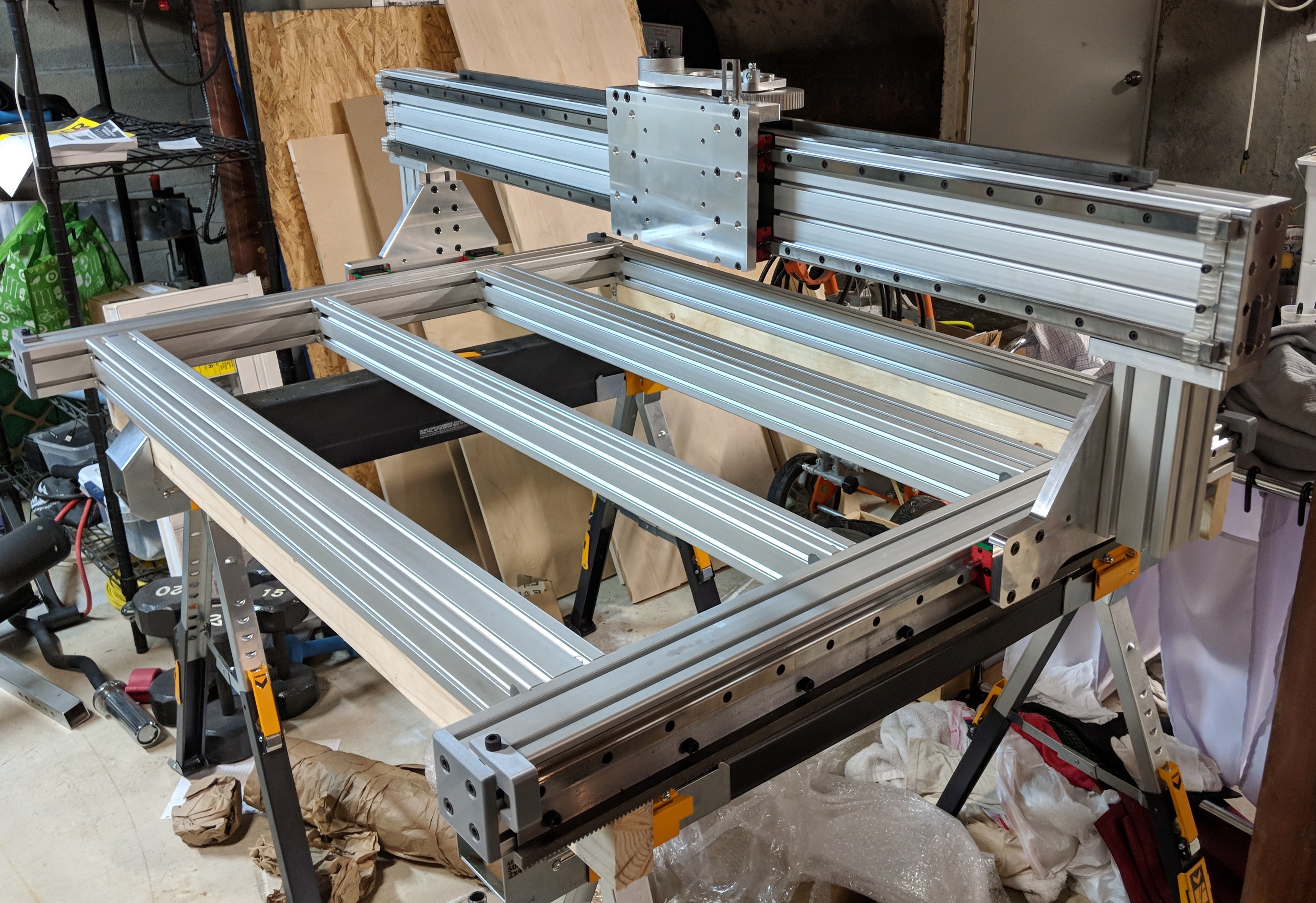
At long last, the completion of the riser plates allowed the whole ‘rolling chassis’ of the CNC router to be assembled – a huge milestone for the project!
This concludes the build of the basic chassis of the machine. The fabrication of many additional unique parts is yet to come, and this wasn’t the last time that most of these particular machined parts saw the Tormach – stay tuned.